Automatic monitoring method for plant area network

An automatic monitoring, plant area network technology, applied in data exchange networks, digital transmission systems, electrical components, etc., can solve the problem of difficult to grasp the real-time operation status of key network equipment in real time, and it is difficult to actively detect abnormal communication quality, equipment deterioration, etc. question

Pending Publication Date: 2020-07-17
BENGANG STEEL PLATES
View PDF4 Cites 4 Cited by
  • Summary
  • Abstract
  • Description
  • Claims
  • Application Information

AI Technical Summary

Problems solved by technology

It is difficult to manually collect and analyze data continuously for several days or months on one or more key network nodes in different isolation networks at the same time. Therefore, it is difficult to proactively find abnormal communication quality, but it is not completely impossible. Work equipment deterioration problem
[0006] Moreover, at present, it is difficult for network maintenance engineers to grasp the real-time operation status of key network devices in multiple specific isolated private networks (which can be basic automation networks) at the same time in non-working hours and non-working places (such as home)

Method used


Image

  • Automatic monitoring method for plant area network
  • Automatic monitoring method for plant area network
  • Automatic monitoring method for plant area network

Examples


Embodiment Construction

[0044] The present invention will be further elaborated below in conjunction with the accompanying drawings of the description.

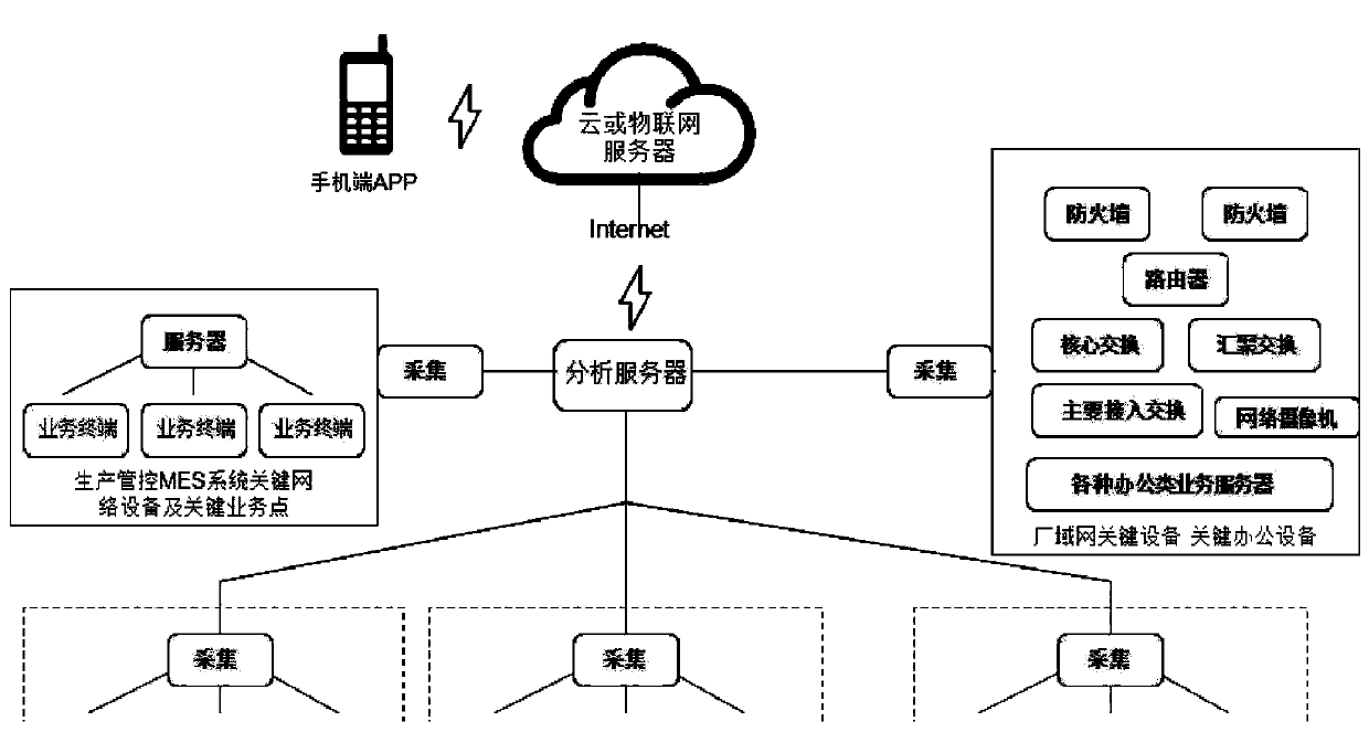
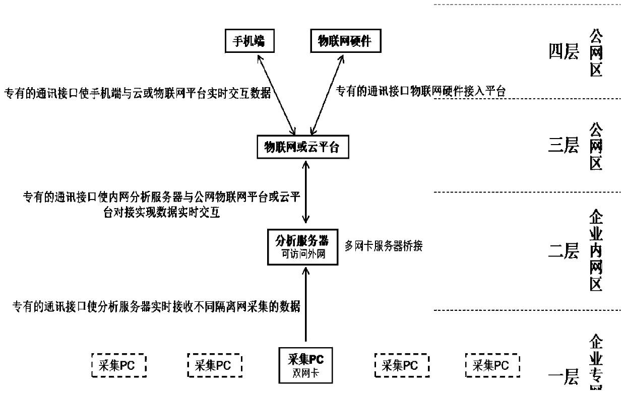
[0045] like Figure 1~2 Shown, a kind of network automatic monitoring method of plant area network of the present invention comprises the following steps:

[0046] 1) Build a network architecture, establish a data collection terminal in the enterprise private network area (first floor) that the manager cares about, establish a data analysis terminal in the enterprise intranet area (second floor), and establish a data analysis terminal in the public network area through the cloud platform or the Internet of Things platform ( The third layer) realizes the data interaction between the enterprise intranet and the public network platform and the mobile terminal (fourth layer) that can realize the interaction with the cloud platform or the Internet of Things platform; the second layer and the first layer can also be the same layer.

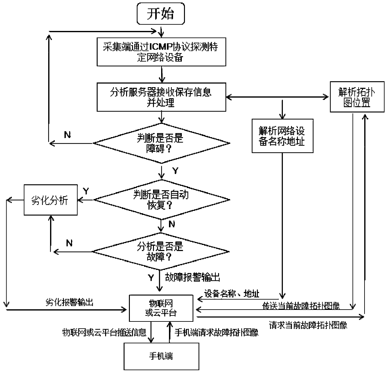
[0047] 2) Arrange netw...


PUM


Abstract

The invention discloses an automatic monitoring method for a plant area network. The method comprises the following steps: establishing a network architecture, establishing a data acquisition terminalin an enterprise private network area concerned by a manager, establishing a data analysis terminal in an enterprise intranet area, realizing data interaction between an enterprise intranet and a public network platform in a public network area through a cloud platform or an Internet of Things platform, and realizing a mobile phone terminal capable of interacting with the cloud platform or the Internet of Things platform; arranging network equipment on each layer, and determining a standard internal communication protocol; in combination with network architecture and network detection, analyzing network faults of network nodes and levels and positions of fault points in an existing topological graph, and pushing network fault information to mobile phones of maintenance personnel through acloud or Internet of Things platform. According to the invention, a daily active detection preventive mode is adopted to replace an original passive fire-fighting processing mode that after a networkfault occurs, a service obstacle is reported, and then network maintenance personnel arrive at the site for maintenance, so that problems can be actively discovered, and the influence on on-site production and service use can be shortened or avoided.

Description

technical field [0001] The invention relates to a network monitoring technology and a network automatic monitoring method of a factory area network (required to buckle the question here). Background technique [0002] At present, efficient enterprise production and operation cannot be separated from the support of computer system and network environment. As the basic physical neural network of enterprise operation, automated production, office, video conferencing, remote control, security, Internet of Things, etc., the network plays an important role in the background silently. At the same time, the network is becoming more and more complex, and the types of devices included (especially the Internet of Things also rely on the basic network) are also becoming more and more diverse. Therefore, the difficulty of network maintenance, coverage, number of devices, types of devices, and types of faults are all on the rise. Increased with the development of technology. [0003] In ...

Claims


Application Information

Patent Timeline
IPC IPC(8): H04L12/24H04L29/08
CPCH04L41/044H04L41/0823H04L41/0876H04L41/0654H04L41/0631H04L41/12H04L67/025H04L67/12H04L67/55
Inventor 张羽军
Owner BENGANG STEEL PLATES
Why Eureka
Try Eureka