
Draught fan motor fixing plate interlocking structure for draught fan coil pipes

A motor fixing plate and lock structure technology, which is applied in the field of air conditioning, can solve the problems that the force and loosening of the fixing bolts cannot be reduced, and the elastic deformation of the top of the air supply box cannot be reduced, so as to avoid shaking, improve smoothness, The effect of preventing excessive vibration

Active Publication Date: 2020-07-17
王雷
View PDF8 Cites 5 Cited by
  • Summary
  • Abstract
  • Description
  • Claims
  • Application Information

AI Technical Summary

Problems solved by technology

[0006] In order to solve the above technical problems, the present invention provides an interlocking structure of fan motor fixing plates for fan coil units, so as to solve the problem that the existing above application cannot achieve maximum noise reduction and elimination through the mutual cooperation of multiple noise reduction structures. On the one hand, it is reflected in the cooperation between the fan fixing plate and the air supply box, which cannot be multi-positioned to reduce the force and loosening probability of the fixing bolts; on the other hand, after the fan coil is installed on the wall, the elasticity of the top of the air supply box The problem that deformation cannot be reduced and eliminated

Method used


Image

  • Draught fan motor fixing plate interlocking structure for draught fan coil pipes
  • Draught fan motor fixing plate interlocking structure for draught fan coil pipes
  • Draught fan motor fixing plate interlocking structure for draught fan coil pipes

Examples


Embodiment

[0033] as attached figure 1 to attach Figure 8 Shown:

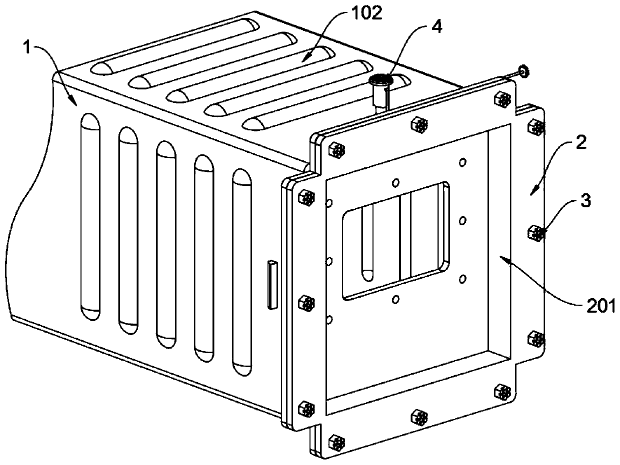
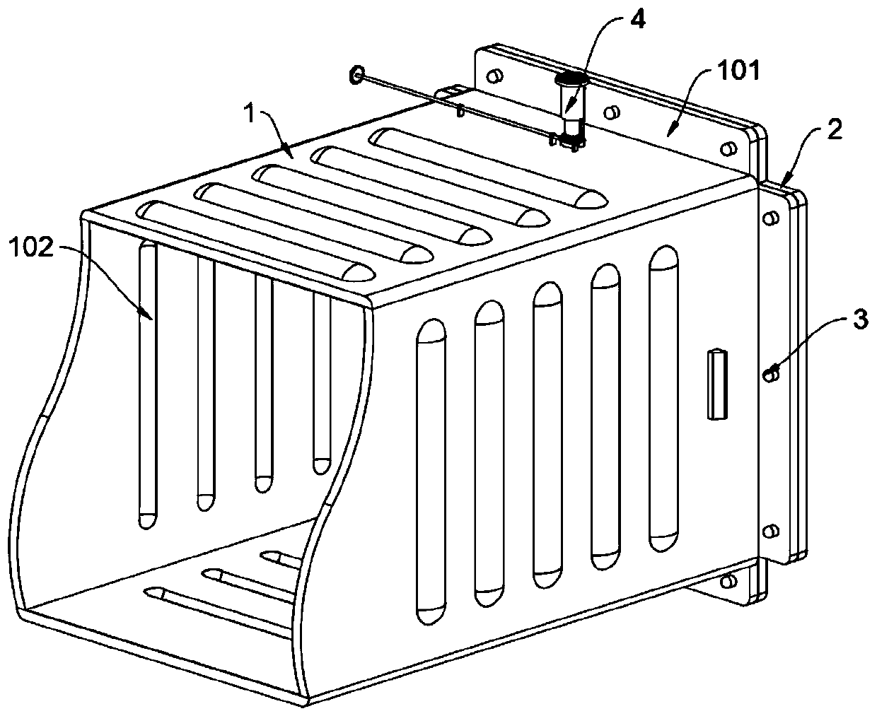
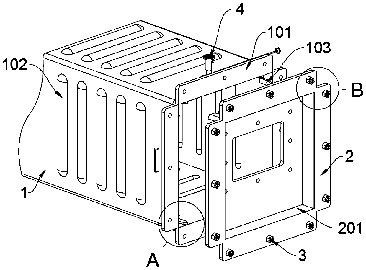
[0034] The present invention provides an interlocking structure of fan motor fixing plates for fan coil units, which includes an air supply box 1; the top surface of the air supply box 1 is fixedly connected with a fan fixing seat 2 through fixing bolts 3, and the top surface of the air supply box 1 is welded There is a supporting noise reduction structure 4; refer to eg Figure 8 The support noise reduction structure 4 also includes a rotating connection seat B406 and a threaded rod B407, the rotating connection seat B406 is welded on the top surface of the air supply box 1, and a threaded rod B407 is rotatably connected to the rotating connection seat B406; the threaded rod B407 and the gear 403 Mesh, and the threaded rod B407 and the gear 403 together form a worm gear structure. At this time, turning the threaded rod B407 can realize the vertical lifting of the threaded pipe 404, which improves the convenience of ad...


PUM


Abstract

The invention provides a draught fan motor fixing plate interlocking structure for draught fan coil pipes, and relates to the field of air conditioners. The problems that multiple limiting cannot be carried out to reduce force bearing and the looseness probability of fixing bolts, and elastic deformation of the top of an air supply box cannot be reduced and eliminated are solved. The draught fan motor fixing plate interlocking structure for the draught fan coil pipes comprises the air supply box. A supporting and noise reducing structure is welded to the top end face of the air supply box. Asa lead screw nut structure is formed by a threaded rod A, a threaded pipe and a telescopic rod jointly, vertical lifting of the threaded pipe can be achieved by rotating the threaded rod A, a turbo-worm structure is formed by a threaded rod B and a gear jointly, at the moment, vertical lifting of the threaded pipe can be achieved by rotating the threaded rod B, the convenience during adjusting isimproved, the threaded pipe vertically rises when the threaded rod B is rotated clockwise, when the top of the threaded pipe abuts against a wall, at the moment, the top end face of the air supply boxis in a bent state, thus, elastic deformation of the top end face of the air supply box can be eliminated, and then vibration is prevented from being generated.

Description

technical field [0001] The invention belongs to the technical field of air conditioning, and more specifically relates to an interlocking structure of a fan motor fixing plate for a fan coil unit. Background technique [0002] In the structure of refrigeration and air-conditioning equipment and refrigeration and air-conditioning terminal equipment, fan coil units have a relatively high utilization rate in major factories, office buildings, hotel rooms and other industries. The noise and performance of the unit are unstable, which often reduces the user experience. [0003] For example, the application number: CN201220269987.3, the utility model discloses an interlocking structure of a fan motor fixing plate for a fan coil unit, which belongs to the technical field of air conditioning. It includes the fan motor fixing plate, the upper cover of the air supply box, the side plate of the surface cooler, and the surface cooler tray; the fan motor fixing plate is a bent plate form...

Claims


Application Information

Patent Timeline
IPC IPC(8): F24F1/0057F24F13/02F24F13/20F24F13/24F24F13/32
CPCF24F13/0227F24F13/20F24F13/24F24F13/32F24F2013/247F24F1/0057
Inventor 张金辉
Owner 王雷
Learn More