
Oil well pump and valve structure

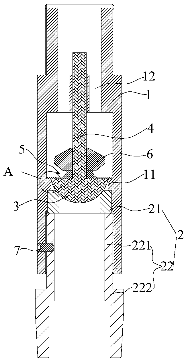
An oil pump and valve technology, applied in the field of oil extraction, can solve the problems affecting oil extraction efficiency, oil return, leakage, etc., to achieve the effect of improving oil extraction efficiency, preventing oil return leakage, and ensuring the sealing effect

Pending Publication Date: 2020-07-17
卫玮
View PDF0 Cites 1 Cited by
  • Summary
  • Abstract
  • Description
  • Claims
  • Application Information

AI Technical Summary

Problems solved by technology

However, in actual use, foreign particles such as sand and stone often appear between the ball and the seat, resulting in a gap between the ball and the seat, so that the pumped oil may flow back, that is, leak, and affect the oil recovery efficiency

Method used


Image

  • Oil well pump and valve structure
  • Oil well pump and valve structure
  • Oil well pump and valve structure

Examples


Embodiment Construction

[0046] Example embodiments will now be described more fully with reference to the accompanying drawings. Example embodiments may, however, be embodied in many forms and should not be construed as limited to the embodiments set forth herein; rather, these embodiments are provided so that this disclosure will be thorough and complete, and will fully convey the concept of example embodiments to those skilled in the art. The same reference numerals in the drawings denote the same or similar structures, and thus their detailed descriptions will be omitted. Furthermore, the drawings are merely schematic illustrations of the present disclosure and are not necessarily drawn to scale.

[0047] Although relative terms such as "upper" and "lower" are used in this specification to describe the relative relationship of one component of an icon to another component, these terms are used in this specification only for convenience, for example, according to the description in the accompanyin...


PUM


Abstract

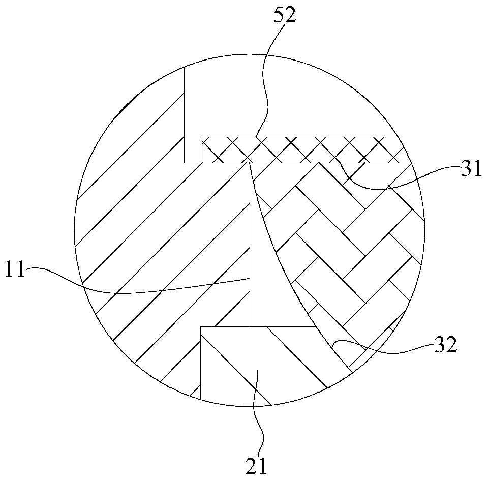
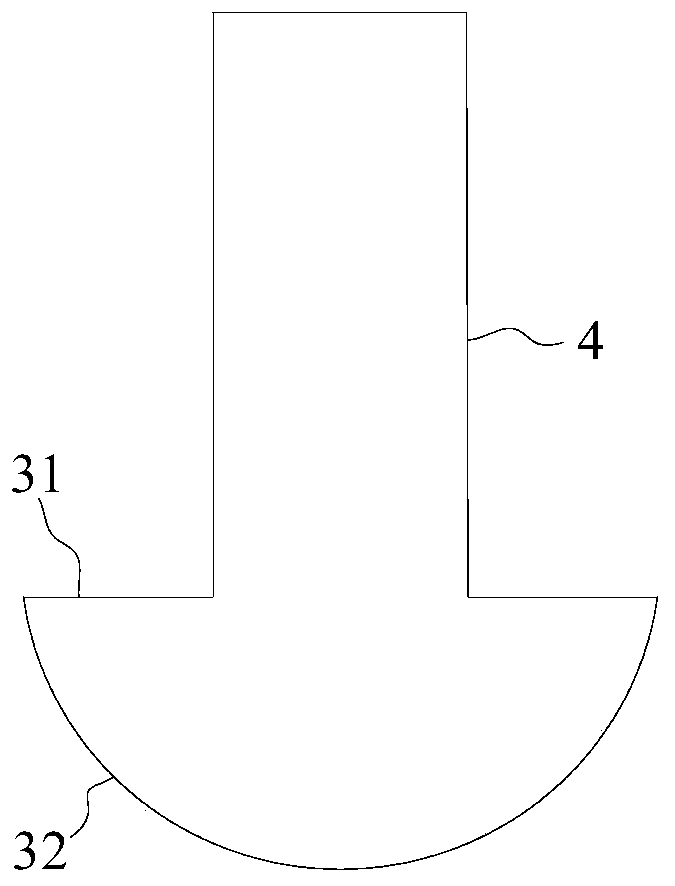
The invention provides an oil well pump and a valve structure, and relates to the technical field of oil exploitation. The valve structure comprises a valve cover, a valve seat, a plugging piece, a guide column and a sealing piece. The valve cover is provided with a first end and a second end which are communicated, the first end is internally provided with a boss, the second end is internally provided with a fixing part, and the fixing part is provided with a guide hole and an oil through hole which are communicated in the axial direction of the valve cover; the valve seat is provided with athrough bottom end part and a through top end part, and the top end part abuts against one side, away from the second end, of the boss; the plugging piece is arranged in the valve cover and comprisesa bottom surface and a side surface surrounding the bottom surface, the side surface is movably abutted with the top end part of the valve seat, the bottom surface faces the second end, the radial size of the plugging piece is equal to the inner diameter of the boss, and the plugging piece is flush with one side, close to the second end, of the boss; one end of the guide column is connected with the bottom surface, and the other end of the guide column slidably penetrates through the guide hole; and the sealing piece is arranged outside the guide column in a sleeving mode, covers the bottom surface and one side, close to the second end, of the boss, and is made of an elastic material.

Description

technical field [0001] The present disclosure relates to the technical field of oil exploitation, in particular, to an oil well pump and a valve structure. Background technique [0002] In the field of oil extraction, the oil pump is an essential equipment, which can lift the crude oil in the well to the ground. Valves are generally used in existing oil well pumps to realize the one-way flow of oil, and Valves are valves. Existing valves are usually opened and closed by contacting or separating valve balls and valve seats. However, in actual use, foreign particles such as sand and stone often appear between the ball and the seat, resulting in a gap between the ball and the seat, so that the pumped oil may flow back, that is, leak, and affect the oil recovery efficiency . [0003] It should be noted that the information disclosed in the above background section is only for enhancing the understanding of the background of the present disclosure, and therefore may include in...

Claims


Application Information

Patent Timeline
Patent Type & Authority Applications(China)
IPC IPC(8): F04B47/00F04B53/10F04B53/00
CPCF04B47/00F04B53/10F04B53/1087F04B53/00
Inventor 卫德义卫玮
Owner 卫玮
Learn More