Eureka AIR delivers breakthrough ideas for toughest innovation challenges, trusted by R&D personnel around the world.

Automatic flood prevention power distribution cabinet for electric power

A power distribution cabinet and electric power technology, applied in substation/power distribution device casing, electrical components, substation/switch layout details, etc., can solve problems such as short circuit inside the cabinet, flooded cabinet, and failure of electrical components to work normally

Active Publication Date: 2021-04-30
JINGZHOU POWER SUPPLY COMPANY STATE GRID HUBEI ELECTRIC POWER
View PDF9 Cites 5 Cited by
  • Summary
  • Abstract
  • Description
  • Claims
  • Application Information

AI Technical Summary

Problems solved by technology

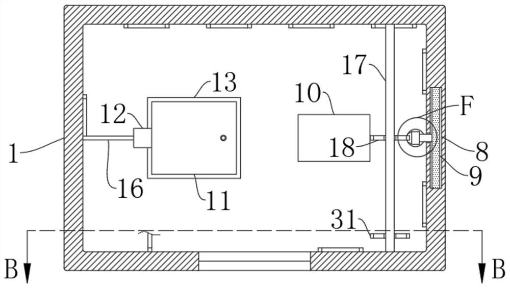
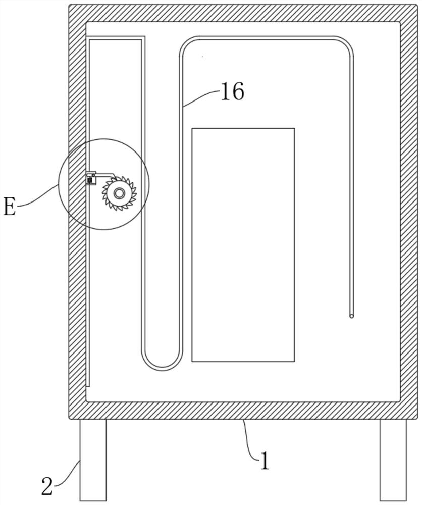
[0003] Traditional power distribution cabinets are generally provided with vents to dissipate heat inside the cabinet. The power distribution cabinets installed in the water power station are located close to the river. During the rainy season, as the water level rises, it is easy to cause the cabinet If the body is flooded, water will enter the cabinet, which will easily cause a short circuit in the circuit inside the cabinet, cause the electrical components inside the cabinet to not work normally, and easily cause electric leakage, causing the staff to have the risk of electric shock when passing by. Therefore, It is necessary to design an automatic flood control distribution cabinet for electric power to solve the above problems

Method used


Image

  • Automatic flood prevention power distribution cabinet for electric power
  • Automatic flood prevention power distribution cabinet for electric power
  • Automatic flood prevention power distribution cabinet for electric power

Examples


Embodiment Construction

[0029] The following will clearly and completely describe the technical solutions in the embodiments of the present invention with reference to the accompanying drawings in the embodiments of the present invention. Obviously, the described embodiments are only some, not all, embodiments of the present invention.

[0030] In describing the present invention, it should be understood that the terms "upper", "lower", "front", "rear", "left", "right", "top", "bottom", "inner", " The orientation or positional relationship indicated by "outside", etc. is based on the orientation or positional relationship shown in the drawings, and is only for the convenience of describing the present invention and simplifying the description, rather than indicating or implying that the referred device or element must have a specific orientation, so as to Specific orientation configurations and operations, therefore, are not to be construed as limitations on the invention.

[0031] refer to Figure ...


PUM


Abstract

The invention discloses anautomatic flood prevention power distribution cabinet for electric power, whichcomprises a cabinet body, wherein four supporting columns are fixedly connected to the lower wall of the cabinet body, a ventilation opening is formed in the side wall of the cabinet body in a penetrating mode, a groove is formed in the inner wall of the ventilation opening, a baffle capable of moving up and down is arranged on the inner wall of the groove, and a sliding groove is formed in the inner wall of the cabinet body and communicates with the groove; the side wall of the baffle is fixedly connected with a connecting rod, and the end, away from the baffle, of the connecting rod is fixedly connected with a rack. When the water surface rises, the baffle blocks the ventilation opening, water can be prevented from entering the cabinet body, normal work of electrical components in the cabinet body is further ensured, the airtightness of the baffle and the groove can be improved through expansion of the air bag, and the waterproof effect of the cabinet body is further improved. Besides, a problem that electrical apparatus elements in the cabinet body are damaged due to the fact that the internal temperature of the cabinet body is too high during sealing can be prevented, repeated use can be achieved, and the economic applicability of the device is improved.

Description

technical field [0001] The invention relates to the technical field of power distribution cabinets, in particular to an automatic flood control power distribution cabinet for electric power. Background technique [0002] The power distribution cabinet is the final equipment of the power distribution system, and it is also the general name of the motor control center. The electric energy of a certain circuit of the upper-level power distribution equipment is distributed to the nearest load. [0003] Traditional power distribution cabinets are generally provided with vents to dissipate heat inside the cabinet. The power distribution cabinets installed in the water power station are located close to the river. During the rainy season, as the water level rises, it is easy to cause the cabinet If the body is flooded, water will enter the cabinet, which will easily cause a short circuit in the circuit inside the cabinet, cause the electrical components inside the cabinet to not w...

Claims


Application Information

Patent Timeline
Patent Type & Authority Applications(China)
IPC IPC(8): H02B1/28H02B1/30H02B1/56H02B1/32
CPCH02B1/28H02B1/30H02B1/565H02B1/32
Inventor 周宇
Owner JINGZHOU POWER SUPPLY COMPANY STATE GRID HUBEI ELECTRIC POWER
Why Eureka
Eureka Blog
Learn More