Exhaust limiting plate for improving energy efficiency of compressor, and compressor

A technology of limit plate and compressor, applied in the field of compressors, can solve the problems of reducing suction efficiency, reducing exhaust volume, exhaust loss, etc. Effect

Pending Publication Date: 2020-07-17
黄石东贝压缩机有限公司
View PDF0 Cites 1 Cited by
  • Summary
  • Abstract
  • Description
  • Claims
  • Application Information

AI Technical Summary

Problems solved by technology

[0002] Piston compressors have suction and exhaust processes during operation. When exhausting, the exhaust valve plate is quickly flapped outward under the impact of high-pressure exhaust gas. To prevent excessive deformation of the valve plate, a lift limit device must be installed to limit The opening angle of the exhaust valve plate and the limit surface of the existing exhaust limit plate are all smooth curves. Although this structure operates reliably, the frequency of opening and closing of the exhaust valve plate is very high, and there will be noise when exhausting. Part of the residual air has not been discharged in time, and the exhaust valve has been closed, resulting in a reduction in exhaust volume and exhaust loss. When the exhaust valve is closed, it mainly depends on the resilience of the valve. When the exhaust valve is closed, the suction valve is closed. If the exhaust valve is not closed fast enough, the high-temperature exhaust will heat the low-temperature gas at the suction end, reducing the suction efficiency

Method used


Image

  • Exhaust limiting plate for improving energy efficiency of compressor, and compressor
  • Exhaust limiting plate for improving energy efficiency of compressor, and compressor
  • Exhaust limiting plate for improving energy efficiency of compressor, and compressor

Examples


Embodiment Construction

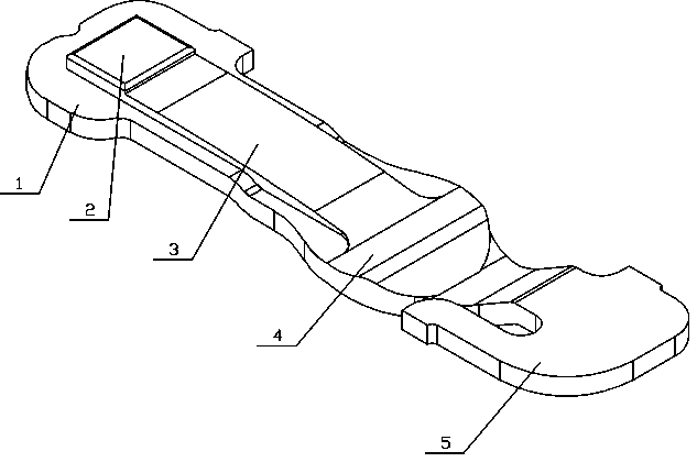
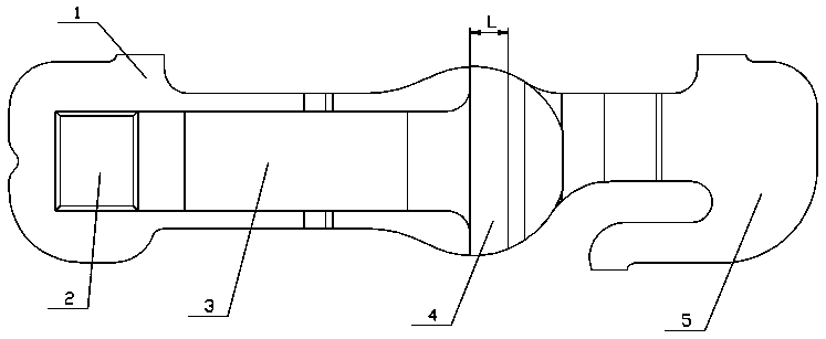
[0017] see Figure 1-6 , this embodiment includes a limiting plate body 1, the periphery of the limiting plate body 1 is matched with the installation groove on the valve plate, and one end of the limiting plate body 1 is provided with a raised portion 2 for pressing the exhaust valve plate 6, the limiting The other end of the plate body 1 is provided with a clamping portion 5 matching the installation groove, and the limiting plate body 1 is provided with a limiting surface 3 from the raised portion 2 to the clamping portion 5, and the exhaust valve plate 6 is limited by the limit surface 3 when it is opened to the maximum angle. The limit surface 3 is provided with a partially concave pit 4 at the end away from the raised part 2. When the exhaust valve plate 6 is opened to the maximum angle First, it is limited by the limiting surface 3, then the tongue of the exhaust valve plate 6 continues to move into the pit 4, and finally rebounds to close.

[0018] The height of the l...


PUM


Abstract

The invention relates to the technical field of compressors, in particular to an exhaust limiting plate for improving the energy efficiency of a compressor. The exhaust limiting plate for improving the energy efficiency of the compressor comprises a limiting plate body, wherein the periphery of the limiting plate body is matched with an installation groove in a valve plate; a lug boss for tightlypressing an exhaust valve plate is arranged at one end of the limiting plate body; a clamping part matched with the installation groove is arranged at the other end of the limiting plate body; the limiting plate body is provided with a liming surface in the direction from the lug boss to the clamping part; the exhaust valve plate is limited by the limiting surface when being opened to a maximum angle; a concave pit concaved locally is arranged at one end, far away from the lug boss, of the limiting surface; and the exhaust valve plate is firstly limited by the limiting surface when being opened to the maximum angle, then a tongue part of the exhaust valve plate continuously moves in the foundation pit, and the exhaust valve plate is finally rebounded and closed. According to the exhaust limiting plate for improving the energy efficiency of the compressor provided by the invention, the energy efficiency of the compressor is improved.

Description

technical field [0001] The invention relates to the technical field of compressors, in particular to an exhaust limiting plate for improving energy efficiency of compressors. Background technique [0002] Piston compressors have suction and exhaust processes during operation. When exhausting, the exhaust valve plate is quickly flapped outward under the impact of high-pressure exhaust gas. To prevent excessive deformation of the valve plate, a lift limit device must be installed to limit The opening angle of the exhaust valve plate and the limit surface of the existing exhaust limit plate are all smooth curves. Although this structure operates reliably, the frequency of opening and closing of the exhaust valve plate is very high, and there will be noise when exhausting. Part of the residual air has not been discharged in time, and the exhaust valve has been closed, resulting in a reduction in exhaust volume and exhaust loss. When the exhaust valve is closed, it mainly depends...

Claims


Application Information

Patent Timeline
Patent Type & Authority Applications(China)
IPC IPC(8): F04B39/10
CPCF04B39/1073
Inventor 杨百昌李华军金盛江罗祥胜
Owner 黄石东贝压缩机有限公司
Why Eureka
Try Eureka