Eureka AIR delivers breakthrough ideas for toughest innovation challenges, trusted by R&D personnel around the world.

Vertical-axis magnetic levitation tidal current energy power generation device and method in combination with offshore horizontal-axis wind turbine tower barrel

A technology of power generation device and horizontal axis, which is applied in the combination of wind turbine and water energy converter, the configuration of installation/support of wind turbine, wind energy generation, etc., to reduce mechanical motion resistance, reduce blade breakage accident rate, and solve parts Effects of wear and replacement problems

Active Publication Date: 2020-07-17
XIAN THERMAL POWER RES INST CO LTD
View PDF7 Cites 5 Cited by
  • Summary
  • Abstract
  • Description
  • Claims
  • Application Information

AI Technical Summary

Problems solved by technology

[0007] The purpose of the present invention is to provide a vertical-axis magnetic levitation tidal current energy generating device and method combined with an offshore horizontal-axis wind turbine tower, which solves how to make full use of the existing offshore wind farm equipment, install a tidal current generator, and then improve the overall efficiency. Field Comprehensive Energy Utilization Efficiency

Method used


Image

  • Vertical-axis magnetic levitation tidal current energy power generation device and method in combination with offshore horizontal-axis wind turbine tower barrel
  • Vertical-axis magnetic levitation tidal current energy power generation device and method in combination with offshore horizontal-axis wind turbine tower barrel
  • Vertical-axis magnetic levitation tidal current energy power generation device and method in combination with offshore horizontal-axis wind turbine tower barrel

Examples


Embodiment Construction

[0035] The present invention will be described in further detail below in conjunction with the accompanying drawings.

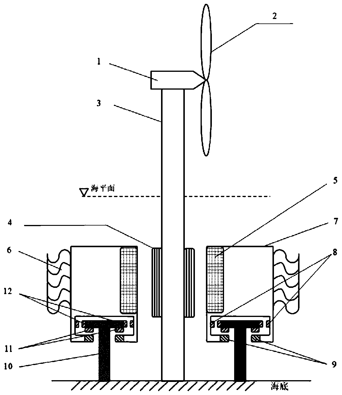
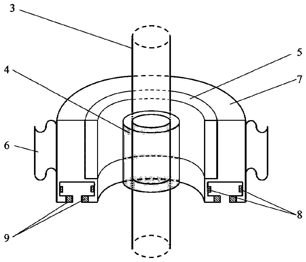
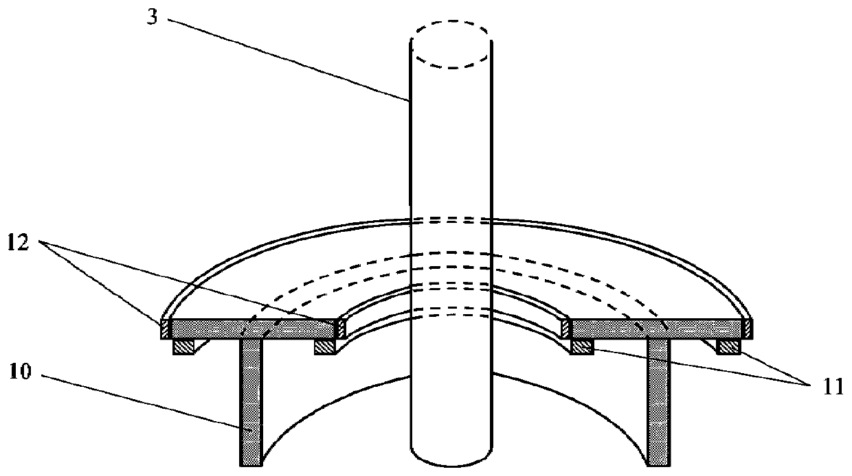
[0036] Such as figure 1As shown, the present invention provides a vertical-axis maglev tidal current energy generation device combined with an offshore horizontal-axis wind turbine tower, including a central unit, a maglev rotor unit and a support unit, wherein the maglev rotor unit is grounded without mechanical contact It is fitted on the central unit and is arranged in a suspended structure under the action of the supporting unit; the top of the supporting unit is located at the bottom of the maglev rotor unit, and its bottom is fixed on the seabed.

[0037] On the basis of the existing offshore wind power generation system, the present invention uses the support unit to fix the rotor unit in a magnetic levitation manner, and uses the magnetic levitation rotor unit and the stator windings set around the horizontal axis wind turbine tower to generate electr...


PUM


Abstract

The invention provides a vertical-axis magnetic levitation tidal current energy power generation device and method in combination with an offshore horizontal-axis wind turbine tower barrel. The vertical-axis magnetic levitation tidal current energy power generation device comprises a central unit, a magnetic levitation rotor unit and a supporting unit, wherein the central unit comprises the horizontal-axis wind turbine single-pile tower barrel and a stator winding. The single-pile tower barrel is fixed to a seabed. The stator winding sleeves the outer wall of the single-pile tower barrel. Themagnetic levitation rotor unit is suspended around the annular stator winding under the action of the supporting unit. The supporting unit is a closed-loop rail with a T-shaped section and is correspondingly arranged below the magnetic levitation rotor unit and fixed to the seabed around the single-pile tower barrel. When a sea tide rises or falls, sea currents push blades to rotate, and magneticpoles of a permanent magnet in the rotor unit are rotated. At the moment, the stator winding installed on the outer wall of the wind turbine single-pile tower barrel converts tidal current kinetic energy into electric energy by cutting rotating magnetic induction lines, and the under-sea tidal current energy power generation method is added on the basis of an existing offshore wind energy power generation system, so that the comprehensive utilization rate of offshore energy is effectively increased.

Description

technical field [0001] The invention belongs to the technical field of offshore tidal current power generation, and relates to a vertical axis magnetic levitation tidal current power generation device and method combined with an offshore horizontal axis wind turbine tower. Background technique [0002] The tidal current mainly refers to the regular sea current generated along with the tidal phenomenon, and its main current changes its size and direction twice a day. Tidal current power generation is in shallow seas, straits, bays or estuaries, directly using the impact of high-speed water caused by rising and ebbing tides to drive a Tidal Stream Generator (TSG) with impellers to convert the kinetic energy of the tidal current into electrical energy. Compared with traditional barrage-type tidal power generation, tidal current power generation avoids the high-cost construction of blocking sea dams, has flexible development scale, and has little impact on the natural ecology of...

Claims


Application Information

Patent Timeline
Patent Type & Authority Applications(China)
IPC IPC(8): F03D9/25F03D1/00F03D13/25F03B13/10F03B3/12H02K7/18
CPCF03B3/12F03B3/121F03B13/10F03D1/00F03D9/008F03D9/25F03D13/25H02K7/1823Y02E10/20Y02E10/30Y02E10/72Y02E10/727
Inventor 韩毅赵勇马勇童博王燕
Owner XIAN THERMAL POWER RES INST CO LTD
Why Eureka
Eureka Blog
Learn More