Permanent magnet reluctance cascade generator control system and control method thereof

A generator control and reluctance technology, applied in the control/regulation system, controlling generators, electrical components and other directions through magnetic field changes, which can solve the problems of uncontrollable excitation of permanent magnet generators, poor low-speed power generation performance, and inability of batteries to start. , to achieve the effect of easy operation, improved reliability and simple control method

Active Publication Date: 2020-10-30
YANGZHOU UNIV
View PDF6 Cites 3 Cited by
  • Summary
  • Abstract
  • Description
  • Claims
  • Application Information

AI Technical Summary

Problems solved by technology

[0003] The purpose of the present invention is to provide a permanent magnet reluctance cascaded generator control system and its control method, which are used to solve the problems of poor low-speed power generation performance, damaged battery, low efficiency of electric excitation, The problem of uncontrollable excitation of permanent magnet generators can improve the power generation performance of vehicle generators in a wide speed range

Method used


Image

  • Permanent magnet reluctance cascade generator control system and control method thereof
  • Permanent magnet reluctance cascade generator control system and control method thereof
  • Permanent magnet reluctance cascade generator control system and control method thereof

Examples


Embodiment Construction

[0036] The present invention will be further described below in conjunction with specific embodiments.

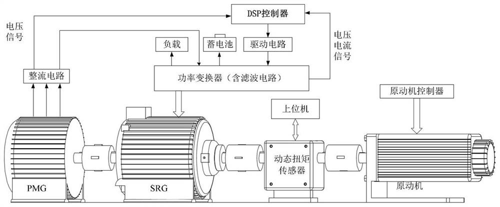
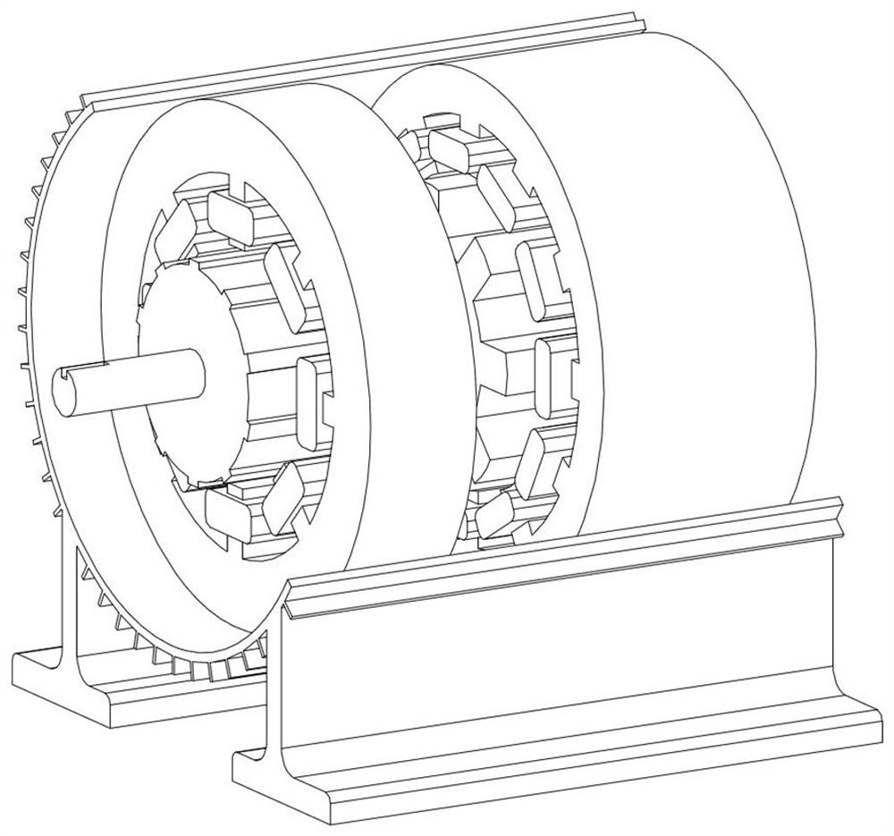
[0037] Such as figure 1 A permanent magnet reluctance cascaded generator control system is shown, including coaxial series permanent magnet generators (permanent magnet synchronous generators or brushless DC generators, PMG for short) and switched reluctance generators (SRG) , in order to reduce the size of the motor, such as figure 2 As shown, the couplings of the two generators can be removed, and the two generators are processed in one casing with one shaft. The rotating shafts of PMG and SRG are connected to the prime mover through the dynamic torque sensor, and the power output is simulated by the prime mover. The given power drives PMG and SRG to work, and this embodiment also includes:

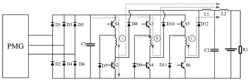
[0038] The rectifier circuit is a three-phase uncontrollable rectifier circuit connected to the PMG to convert the output of the PMG into direct current and output it to the power...


PUM


Abstract

The invention discloses a permanent magnet reluctance cascade generator control system, which comprises a PMG and an SRG which are coaxially connected in series, and further comprises a rectifying circuit which selects a three-phase uncontrollable rectifying circuit, is connected with the PMG and is used for converting PMG output into direct current and outputting the direct current to a power converter, the power converter adopts a separately excited asymmetric half-bridge structure, is connected with the SRG, is used for controlling the SRG to work, and can further output electric energy atthe same time, the DSP controller is connected with the rectifying circuit and the power converter and used for collecting corresponding voltage and current signals and outputting driving signals through the driving circuit to control the power converter to work, the overall reliability of the system is improved, the safety coefficient is increased, the control mode is simple, and operation is easy.

Description

technical field [0001] The invention relates to a generator, in particular to a permanent magnet reluctance cascaded generator. Background technique [0002] At present, the vehicle power generation system uses a single motor to generate power, and most generators use electric excitation generators. This makes the excitation voltage of the generator only obtained from the battery, and cannot guarantee normal operation when the battery is dead or damaged. The magnetic field of the electric excitation generator is generated by the electrification of the winding coil, which leads to low efficiency of the generator and a decrease in power density. Permanent magnet generators (PMG) have high efficiency and high power density, but the inherent characteristics of permanent magnets make the magnetic field strength uncontrollable, and the output voltage needs to be adjusted by a corresponding controllable rectifier. Contents of the invention [0003] The purpose of the present inv...

Claims


Application Information

Patent Timeline
Patent Type & Authority Applications(China)
IPC IPC(8): H02P9/14H02P9/30H02M7/217H02M3/158
CPCH02P9/14H02P9/30H02M7/217H02M3/1582
Inventor 王千龙景鑫蒋伟于照蒋步军
Owner YANGZHOU UNIV
Why Eureka
Try Eureka