
Crankshaft and flywheel set

A flywheel and crankshaft technology, applied in flywheels, electric components, electromechanical devices, etc., can solve the problem of the single role of flywheel energy storage, and achieve the effect of avoiding transmission failures and power loss

Pending Publication Date: 2020-07-17
广西玉柴船电动力有限公司
View PDF0 Cites 1 Cited by
  • Summary
  • Abstract
  • Description
  • Claims
  • Application Information

AI Technical Summary

Problems solved by technology

But the existing flywheel mainly plays a single role of energy storage

Method used


Image

  • Crankshaft and flywheel set
  • Crankshaft and flywheel set
  • Crankshaft and flywheel set

Examples


Embodiment Construction

[0015] The specific embodiments of the present invention will be described in detail below in conjunction with the accompanying drawings, but it should be understood that the protection scope of the present invention is not limited by the specific embodiments.

[0016] Unless expressly stated otherwise, throughout the specification and claims, the term "comprise" or variations thereof such as "includes" or "includes" and the like will be understood to include the stated elements or constituents, and not Other elements or other components are not excluded.

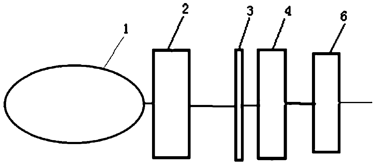
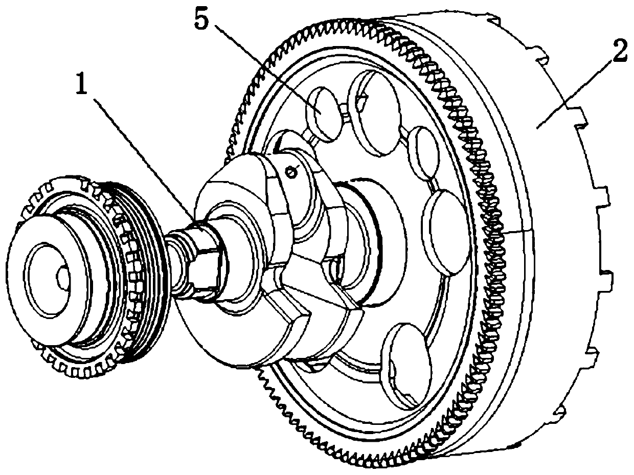
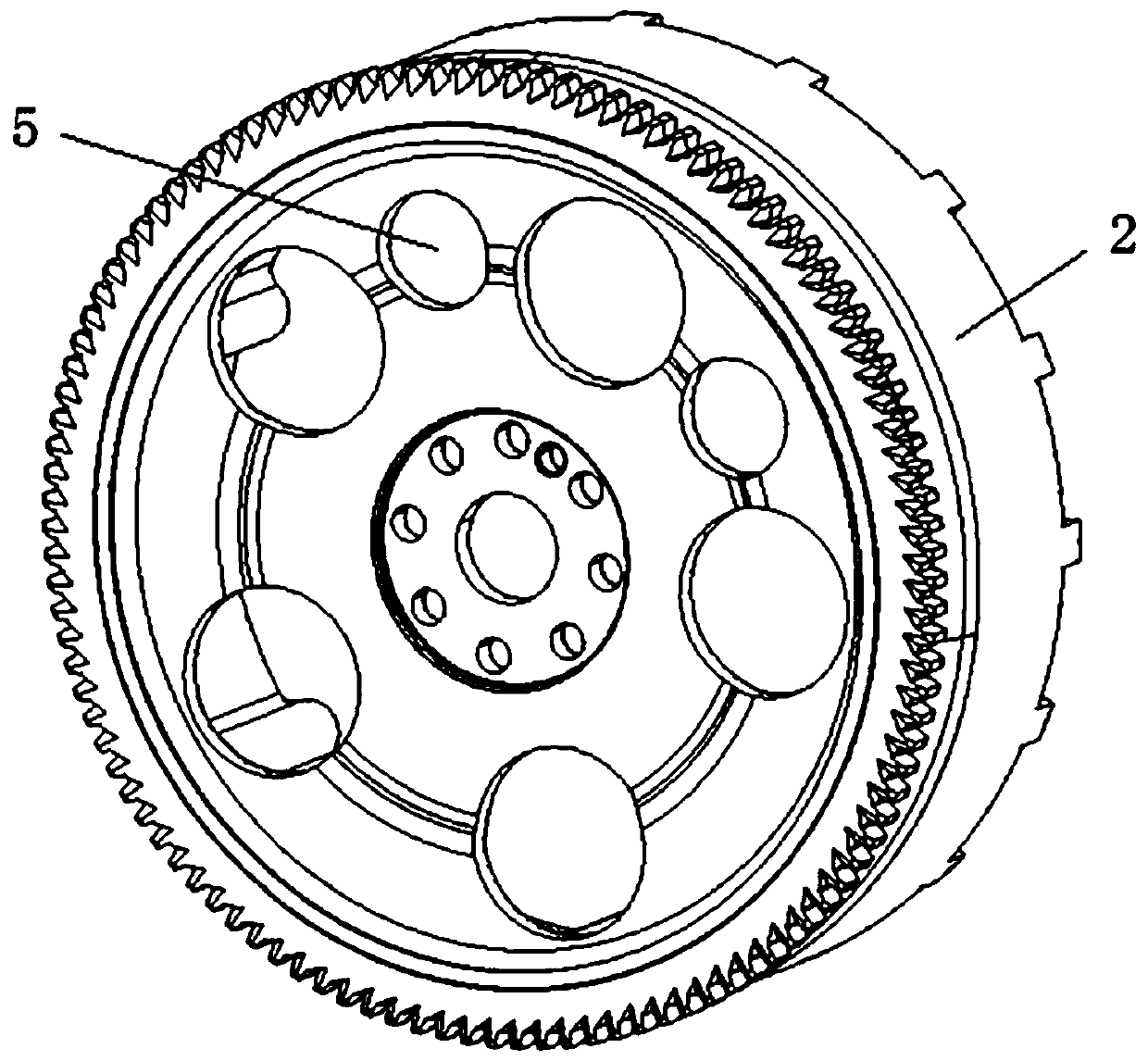
[0017] Such as figure 1 and figure 2 As shown, the specific structure of the crankshaft flywheel assembly according to the preferred embodiment of the present invention includes: crankshaft 1 , flywheel 2 , magnet 3 and coupling coil 4 . The function of the crankshaft flywheel is to convert the reciprocating motion of the piston into the rotational motion of the crankshaft, and output torque for the running of the car an...


PUM


Abstract

The invention discloses a crankshaft and flywheel set. The crankshaft and flywheel set comprises a crankshaft, a flywheel and a rotor rotating magnetic field assembly, a belt wheel is mounted at one end of the crankshaft, the flywheel is mounted on the other end of the crankshaft, the rotor rotating magnetic field assembly comprises a magnet and a coupling coil, the magnet and the coupling coil are arranged on the flywheel to serve as a generator rotor, along with the flywheel rotation, a rotating magnetic field is formed, a generator stator coil matched with the generator rotor cuts a magnetic line to generate induction current, according to the crankshaft and flywheel set, the magnet and the coupling coil are arranged on the flywheel to serves as the generator rotor to form the rotatingmagnetic field, the generator stator coil cuts the magnetic line to generate the induction current, through a rectifier, power is output, the flywheel of the crankshaft and flywheel set serves as thegenerator rotor, a transmission system of an engine and a generator in a hybrid system can be omitted, and power losses and faults of the transmission aspect can be avoided.

Description

technical field [0001] The invention relates to the field of engines, in particular to a crankshaft flywheel set. Background technique [0002] The crankshaft flywheel set is mainly composed of crankshaft, flywheel and other parts and accessories with different functions. The type and quantity of its parts and accessories depend on the structure and performance requirements of the engine. The function of the crankshaft flywheel is to convert the reciprocating motion of the piston into the rotational motion of the crankshaft, and output torque for the running of the car and other mechanisms that require power. At the same time, energy is also stored to overcome the resistance of the non-working stroke and make the engine run smoothly. [0003] Among them, the flywheel has a large moment of inertia. Since the work done by each cylinder of the engine is discontinuous, the engine speed also changes. In the power stroke, the energy transmitted by the engine to the crankshaft,...

Claims


Application Information

Patent Timeline
IPC IPC(8): F02B63/04H02K7/18F16F15/30
CPCF02B63/042F16F15/30H02K7/1846
Inventor 黄第云张寿权蔡小伟
Owner 广西玉柴船电动力有限公司
Learn More