Connecting structure of prefabricated building
A connection structure and prefabricated technology, applied in building components, building structures, buildings, etc., can solve the problems of heavy binding or welding workload, difficult connection quality assurance, low assembly rate of prefabricated buildings, etc. Shorten the construction period, improve the efficiency of assembly and construction, and the effect of reliable connection
- Summary
- Abstract
- Description
- Claims
- Application Information
AI Technical Summary
Problems solved by technology
Method used
Image


Examples
Embodiment 1
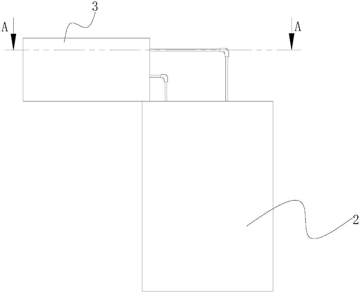
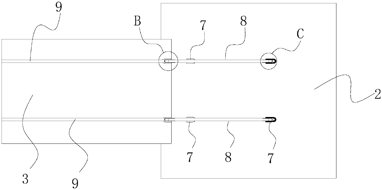
[0089] Such as figure 1 As shown, the connection structure between the prefabricated beam and the prefabricated column provided in this embodiment includes the lower prefabricated column 2, the first prefabricated beam 3, several connectors 7 and several extension rods 8, the connector 7 has a connector body, and the connector The body is provided with more than two connection ends, and the connector 7 is placed in the connection space formed by the combination of the lower prefabricated column 2 and the first prefabricated beam 3, and several stress tendons ( not shown in the figure), these stress tendons are exposed toward the end of the connecting space, and the extension rods 8 correspond to the stress tendons one by one, and the two ends of each extension rod 8 are respectively connected to the corresponding connector 7 and the corresponding Stress tendons connect the lower prefabricated column 2 with the first prefabricated beam 3, and the connecting space is filled with...
Embodiment 2
[0105] Such as Figure 19 with Figure 20 As shown, the connection structure between the prefabricated beam and the prefabricated column provided in this embodiment is basically the same as the connection structure between the prefabricated beam and the prefabricated column provided in Example 1, and will not be repeated here. The difference is that in this embodiment The inner threaded end provided at one end of the stress rib 9 is a connecting nut 12, one end of the connecting nut 12 is provided with a threaded hole, the extension rod 8 is screwed with the connecting nut 12, and the center of the end of the connecting nut 12 away from the threaded hole is provided with an internal large There is a small stepped hole on the outside and a clamping platform 13 is formed around the stepped hole, and the clamping platform 13 of the connecting nut 12 is clamped with the header 14 at the connecting end of the stress rib 9 . The inner threaded end is a connecting nut 12, and the ce...
Embodiment 3
[0107] Such as Figure 21 with Figure 22 As shown, the connection structure between the prefabricated beam and the prefabricated column provided in this embodiment is basically the same as the connection structure between the prefabricated beam and the prefabricated column provided in Example 1, and will not be repeated here. The difference is that in this embodiment , the inner threaded end provided at one end of the stressed rib 9 is a straight threaded sleeve 15, one end of the extension rod 8 is screwed with one end of the straight threaded sleeve 15, and the other end of the straight threaded sleeve 15 is connected with the screw at one end of the stressed rib 9. The column phase is screwed. The stud at one end of the tendon 9 stretches out of the prefabricated beam or the prefabricated column. The inner threaded end is a straight threaded sleeve 15, one end of the extension rod 8 is screwed to one end of the straight threaded sleeve 15, and the other end of the straig...
PUM
 Abstract
Description
Claims
Application Information
 - R&D
- Intellectual Property
- Life Sciences
- Materials
- Tech Scout
- Unparalleled Data Quality
- Higher Quality Content
- 60% Fewer Hallucinations
Browse by: Latest US Patents, China's latest patents, Technical Efficacy Thesaurus, Application Domain, Technology Topic, Popular Technical Reports.
© 2025 PatSnap. All rights reserved.Legal|Privacy policy|Modern Slavery Act Transparency Statement|Sitemap|About US| Contact US: help@patsnap.com