A waste plastic cutting and crushing device
A technology for cutting, crushing and waste plastics, which is applied in plastic recycling, mechanical material recycling, recycling technology, etc. It can solve the problems of low work efficiency and insufficient crushing, and achieve the effect of increasing efficiency.
- Summary
- Abstract
- Description
- Claims
- Application Information
AI Technical Summary
Problems solved by technology
Method used
Image

Examples
specific Embodiment approach 1
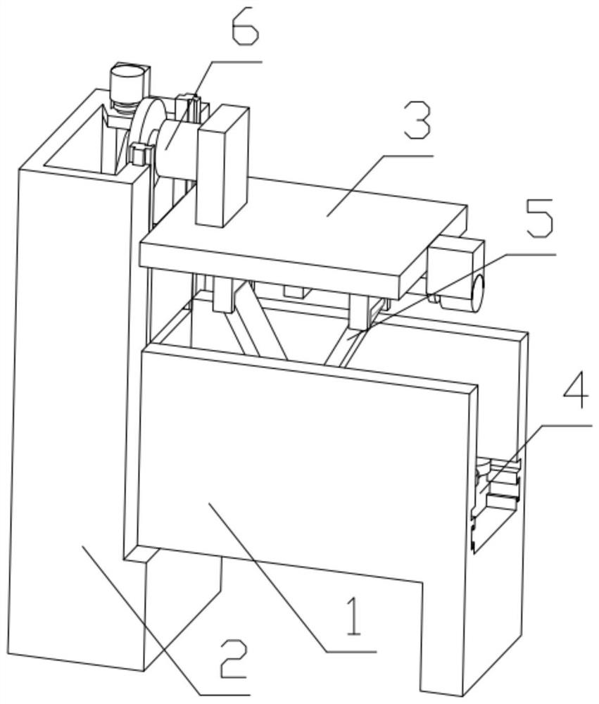
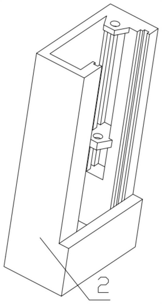
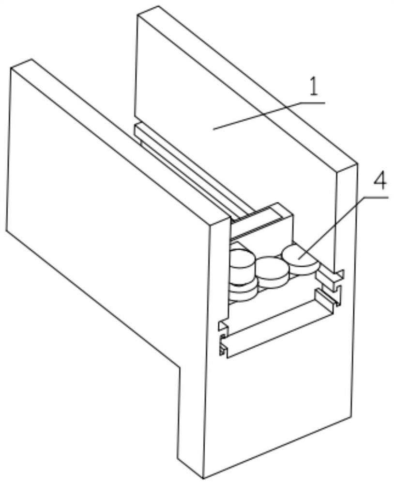
[0034] Combine below Figure 1-14 Describe this embodiment, a waste plastic cutting and crushing device, including a mechanism mounting frame 1, a mechanism mounting frame 2 2 and a mechanism mounting top plate 3, the mechanism mounting frame 1 is fixedly connected to the mechanism mounting frame 2 2, and the mechanism mounting frame 2 2 Fixedly connected with the mechanism installation top plate 3, the plastic propulsion mechanism 4 is installed on the mechanism installation frame one 1, the plastic pressing mechanism 5 is fixedly installed on the mechanism installation top plate 3, and the plastic cutting mechanism 6 is installed on the mechanism installation frame two 2.
specific Embodiment approach 2
[0035] Combine below Figure 1-14Illustrate this embodiment, this embodiment will further explain Embodiment 1, the described plastic propulsion mechanism 4 includes L-shaped pusher 4-1, moving gear 1 4-2, main gear 4-3, auxiliary gear 4-4, Mobile gear two 4-5, displacement motor 4-6, movable plate 4-7, inner support spring 4-8, inner support spring 4-8 are fixedly installed in the groove that L shape pusher 4-1 is provided with, The movable plate 4-7 is slidably installed in the groove provided on the L-shaped pusher 4-1, the movable plate 4-7 is fixedly connected with the inner support spring 4-8, and the displacement motor 4-6 is fixedly installed on the L-shaped pusher On 4-1, pinion gear 4-4 is fixedly installed on the output end of displacement motor 4-6, pinion gear 4-4 is meshed with mobile gear 2 4-5, and main gear 4-3 is in phase with pinion gear 4-4. meshing, the main gear 4-3 is meshed with the mobile gear 4-2, the main gear 4-3 is rotatably installed on the groov...
specific Embodiment approach 3
[0036] Combine below Figure 1-14 Describe this embodiment, this embodiment will further explain the first embodiment, the plastic pressing mechanism 5 includes a pressing plate 5-1, a U-shaped hinge 5-2, a swinging plate 5-3, a threaded moving part 5-4, Limiting ring 5-5, bidirectional threaded rod 5-6, pressing motor 5-7, motor base 5-8, pressing plate 5-1 is fixedly connected with U-shaped hinge 5-2, U-shaped hinge 5-2 Hinged with the swing plate 5-3, the swing plate 5-3 is hinged with the threaded moving part 5-4, the threaded moving part 5-4 is threaded with the two-way threaded rod 5-6, and the two-way threaded rod 5-6 is connected with the limit ring 5-5 is fixedly connected, the two-way threaded rod 5-6 is fixedly installed on the output end of the pressing motor 5-7, the pressing motor 5-7 is fixedly installed on the motor base 5-8, and the motor base 5-8 is fixedly installed on the mechanism Install on the top plate 3, the limit ring 5-5 is rotated and installed on ...
PUM
 Abstract
Description
Claims
Application Information
 - R&D
- Intellectual Property
- Life Sciences
- Materials
- Tech Scout
- Unparalleled Data Quality
- Higher Quality Content
- 60% Fewer Hallucinations
Browse by: Latest US Patents, China's latest patents, Technical Efficacy Thesaurus, Application Domain, Technology Topic, Popular Technical Reports.
© 2025 PatSnap. All rights reserved.Legal|Privacy policy|Modern Slavery Act Transparency Statement|Sitemap|About US| Contact US: help@patsnap.com