
Ultrasonic cake-cutting machine convenient for inserting paper

An ultrasonic and cutting machine technology, which is applied in the division/slicing of baked food, conveyor objects, sending objects, etc., can solve the problem of low paper insertion efficiency and achieve the effect of convenient paper insertion

Active Publication Date: 2020-07-17
CHEERSONIC ULTRASONICS CO LTD
View PDF21 Cites 0 Cited by
  • Summary
  • Abstract
  • Description
  • Claims
  • Application Information

AI Technical Summary

Problems solved by technology

After the cake is cut, insert cake paper at the cutting position to separate the cut cakes. The existing ultrasonic cake cutting machine also has the function of inserting paper, but it can only insert paper one by one. less efficient

Method used


Image

  • Ultrasonic cake-cutting machine convenient for inserting paper
  • Ultrasonic cake-cutting machine convenient for inserting paper
  • Ultrasonic cake-cutting machine convenient for inserting paper

Examples


Embodiment 1

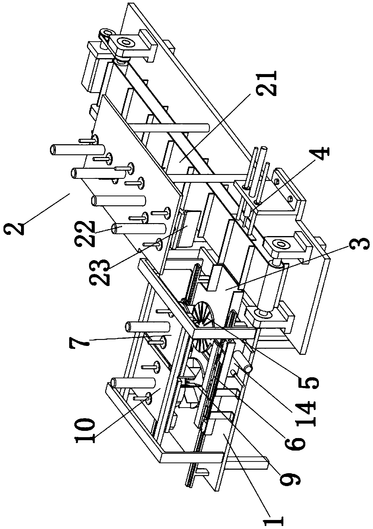
[0047] An ultrasonic cake cutter for easy paper insertion, including:

[0048] Rack 1;

[0049]Cutting assembly 2, the cutting assembly 2 is installed on the frame 1;

[0050] The first guide seat 3, the first guide seat 3 is located on one side of the cutting assembly 2;

[0051] The first pusher assembly 4, the first pusher assembly 4 is located on the other side of the cutting assembly 2;

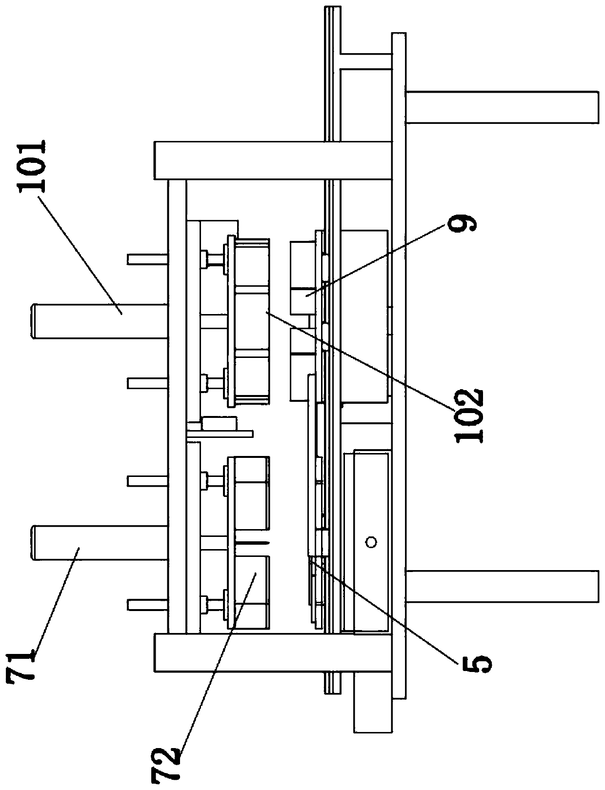
[0052] The material receiving plate 5 is located above the first guide seat 3, the material receiving plate 5 is provided with a first through hole 51, and the material receiving plate 5 is slidably connected with the frame 1;

[0053] The first driving assembly 6, the first driving assembly 6 is installed on the frame 1, the first driving assembly 6 is connected with the material receiving plate 5 for driving the material receiving plate 5 to slide;

[0054] The paper insertion assembly 7, the paper insertion assembly 7 is located above the receiving plate 5;

[0055] The first slid...

Embodiment 2

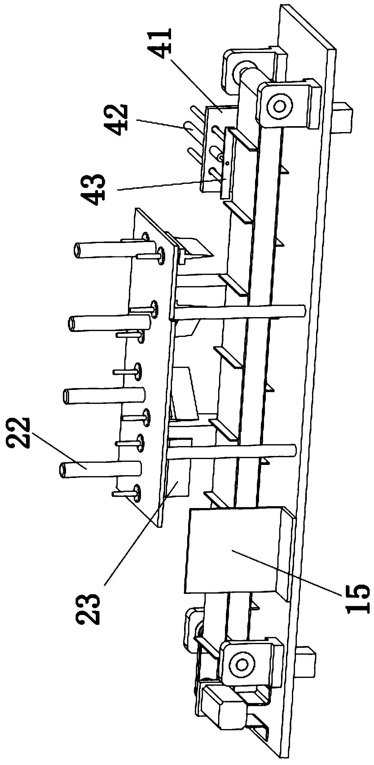
[0070] Such as Figure 9 with Figure 10 As shown, in this embodiment, the cutting assembly 2 includes a conveyor belt assembly 21 and a cutting knife assembly, the cutting knife assembly is installed above the conveyor belt assembly 21, guide grooves are provided on the conveyor belt assembly 21, and at least four groups of cutting knife assemblies are arranged at intervals .

[0071] In this way, the conveyor belt assembly 21 drives the cake to move to the bottom of different cutting knife assemblies in turn, and the cutting knife assembly cuts the cake. When the cake is cut by the last cutting knife assembly, the whole cake is cut. In the transmission of the conveyor belt assembly 21, the cakes arranged sequentially on the conveyor belt assembly 21 are cut by the cutting knife assembly one by one, and the cake located at the front has been cut. This cutting method has higher cutting efficiency.

[0072] In addition, the first pushing assembly 4 includes a second fixing se...

Embodiment 3

[0079] In this embodiment, the ultrasonic cutter 23 includes a cutter body 231, a transducer housing 232, a transducer, a horn 233 and a cooling assembly, and the output shaft of the fifth linear motion power device 22 is connected to the transducer housing 232 , the transducer is fixed in the transducer shell 232, the horn 233 is fixed on the transducer shell 232, the horn 233 is connected with the transducer, the cutter body 231 is connected with the horn 233; the cutter body 231 The upper end is provided with a receiving cavity 2311 and a second through hole connected to the receiving cavity 2311. There are two receiving cavities 2311 at intervals. The receiving cavity 2311 is provided with openings. The openings of the two receiving cavities 2311 face two opposite directions to dissipate heat. The components are provided with two groups, and the two groups of cooling components are respectively installed corresponding to the two accommodating cavities 2311; the cooling comp...


PUM


Abstract

The invention relates to an ultrasonic cake-cutting machine convenient for inserting paper. The machine comprises a machine frame, a cutting component, a first guide seat, a first material pushing component, a material receiving plate, a first driving component, a paper inserting component, a first sliding seat, a material placement disk and a paper sucking component; the cutting component is installed on the machine frame; the first guide seat is located on one side of the cutting component; the first material pushing component is located on the other side of the cutting component; the material receiving plate is located above the first guide seat, the material receiving plate is provided with a first through hole, and the material receiving plate is slidingly connected with the machine frame; the first driving component is installed on the machine frame, and the first driving component is connected with the material receiving plate; the paper inserting component is located above thematerial receiving plate; the first sliding seat is located on one side of the material receiving plate, the first sliding seat is slidably installed on the machine frame, and the first sliding seat is fixedly connected with the material receiving plate; the material placement disk is installed on the first sliding seat; and the paper sucking component is located above the material placement disk.After the solution is adopted, paper can be conveniently inserted into the cut cake.

Description

technical field [0001] The invention relates to an ultrasonic cake cutting machine which is convenient for paper insertion. Background technique [0002] Cake is a kind of dessert that people often eat. The cake needs to be cut before serving. At the same time, cake paper is inserted at the cutting position to separate the cut cakes. When the number of cut cakes is small, manual cutting can also meet the demand. However, in some occasions where the demand for cakes is large, a large number of cakes need to be cut. If only relying on manual operations, the efficiency is low. Therefore, people invented the ultrasonic cake cutting machine, which uses the ultrasonic cutting knife to cut the cake quickly, and the cake will not stick to the cutting knife, so it is widely used. After the cake is cut, insert cake paper at the cutting position to separate the cut cakes. The existing ultrasonic cake cutting machine also has the function of inserting paper, but it can only insert pape...

Claims


Application Information

Patent Timeline
Patent Type & Authority Applications(China)
IPC IPC(8): A21C15/04B65G47/82B65H29/24
CPCA21C15/04B65G47/82B65H29/24
Inventor 李捷飞张志明赵宁飞李霞杨丽娜凌小琴
Owner CHEERSONIC ULTRASONICS CO LTD
Learn More