
An ultrasonic cake cutting machine

An ultrasonic and cutting machine technology, which is applied in the division/slicing of baked food, can solve the problem of low paper insertion efficiency, and achieve the effect of high paper insertion efficiency and convenient paper insertion

Active Publication Date: 2021-12-14
舒城县河棚科技创新协会
View PDF9 Cites 0 Cited by
  • Summary
  • Abstract
  • Description
  • Claims
  • Application Information

AI Technical Summary

Problems solved by technology

After the cake is cut, insert cake paper at the cutting position to separate the cut cakes. The existing ultrasonic cake cutting machine also has the function of inserting paper, but it can only insert paper one by one. less efficient

Method used


Image

  • An ultrasonic cake cutting machine
  • An ultrasonic cake cutting machine
  • An ultrasonic cake cutting machine

Examples


Embodiment 1

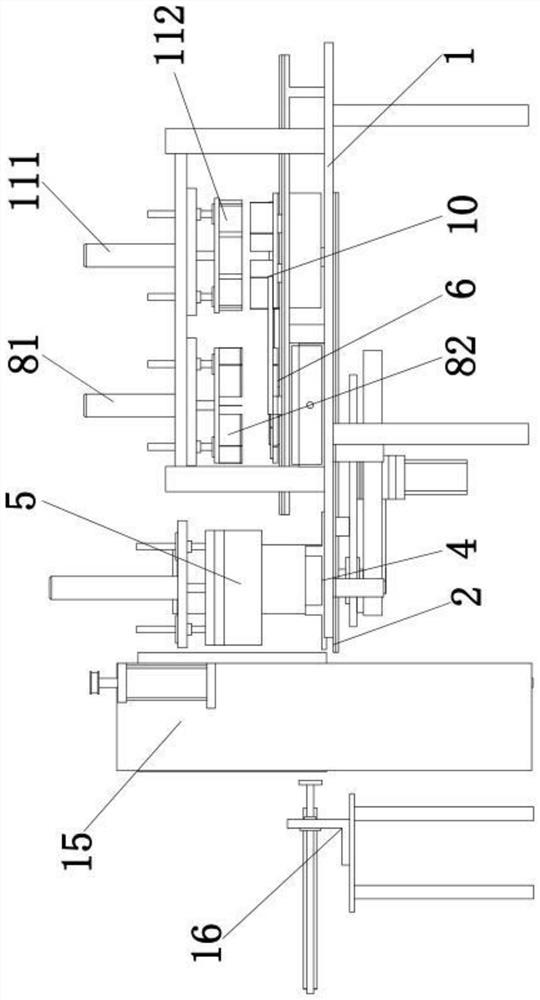
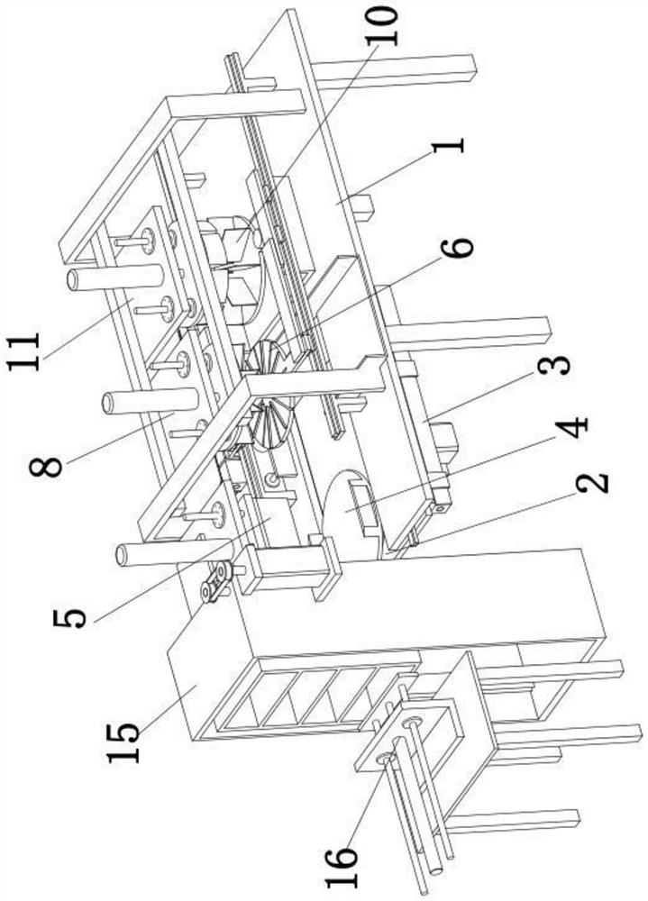
[0047] An ultrasonic cake cutting machine, comprising:

[0048] Rack 1;

[0049] The first sliding seat 2, the first sliding seat 2 is slidably connected with the frame 1;

[0050] The first driving assembly 3, the first driving assembly 3 is installed on the frame 1, and the first driving assembly 3 is connected with the first sliding seat 2;

[0051] The cake turntable assembly 4, the cake turntable assembly 4 is installed on the first sliding seat 2;

[0052] Cutting assembly 5, the cutting assembly 5 is installed above the cake turntable assembly 4;

[0053] The material receiving plate 6 is located above the cake turntable assembly 4, the material receiving plate 6 is provided with a through hole 61, and the material receiving plate 6 is slidably connected with the frame 1;

[0054] The second driving assembly 7, the second driving assembly 7 is installed on the frame 1, and the second driving assembly 7 is connected with the receiving plate 6;

[0055] A paper insert...

Embodiment 2

[0071] In this embodiment, the cake turntable assembly 4 includes a turntable 41 and a third drive assembly 42, the turntable 41 is rotatably mounted on the first sliding seat 2, the third drive assembly 42 is connected with the turntable 41 for driving the turntable 41 to rotate, and the turntable 41 A first guide groove is arranged on it.

[0072] In this way, the first guide groove can guide and position the sliding of the cake pan at the bottom of the cake, and the third driving assembly 42 is used to drive the rotation of the turntable.

[0073] In addition, it also includes a first pusher assembly 14, the first pusher assembly 14 is located on the side below the material receiving plate, and the first pusher assembly 14 includes a first fixed seat 141, a fourth linear motion power device 142 and a first pusher assembly 142. A pusher plate 143, the first fixed seat 141 is fixed on the frame 1, the fourth linear motion power device 142 is fixed on the first fixed seat 141,...


PUM


Abstract

The invention relates to an ultrasonic cake cutting machine, comprising: a frame; a first sliding seat, which is slidably connected to the frame; a first driving assembly, which is connected to the first sliding seat; a cake turntable assembly, The cake turntable assembly is installed on the first sliding seat; the cutting assembly, the cutting assembly is installed above the cake turntable assembly; the material receiving plate, the material receiving plate is located above the cake turntable assembly, and the material receiving plate is slidingly connected with the frame; the second drive assembly, the second drive assembly is installed on the frame, and the second drive assembly is connected with the material receiving plate; the paper insertion assembly, the paper insertion assembly is installed above the material receiving plate; the second sliding seat, the second sliding seat slides with the frame connection, the second sliding seat is fixedly connected with the material receiving plate; the discharge tray, the discharge tray is installed on the second sliding seat; the suction paper assembly, the suction paper assembly is installed above the discharge tray. After adopting such a scheme, paper insertion can be conveniently performed on the cut cake, and the paper insertion efficiency is high.

Description

technical field [0001] The invention relates to an ultrasonic cake cutting machine. Background technique [0002] Cake is a kind of dessert that people often eat. The cake needs to be cut before serving. At the same time, cake paper is inserted at the cutting position to separate the cut cakes. When the number of cut cakes is small, manual cutting can also meet the demand. However, in some occasions where the demand for cakes is large, a large number of cakes need to be cut. If only relying on manual operations, the efficiency is low. Therefore, people invented the ultrasonic cake cutting machine, which uses the ultrasonic cutting knife to cut the cake quickly, and the cake will not stick to the cutting knife, so it is widely used. After the cake is cut, insert cake paper at the cutting position to separate the cut cakes. The existing ultrasonic cake cutting machine also has the function of inserting paper, but it can only insert paper one by one. less efficient. Content...

Claims


Application Information

Patent Timeline
Patent Type & Authority Patents(China)
IPC IPC(8): A21C15/04
CPCA21C15/04
Inventor 夏鲁彬张稳
Owner 舒城县河棚科技创新协会
Learn More