
Self-propelled bundling machine

A self-propelled, baler technology, used in packaging, loaders, agricultural machinery and implements, etc., can solve problems such as the inability of the baler to work independently, the inability to continuously complete the collection operation, and the shutdown of the round baler.

Pending Publication Date: 2020-07-17
CHINESE ACAD OF AGRI MECHANIZATION SCI
View PDF0 Cites 1 Cited by
  • Summary
  • Abstract
  • Description
  • Claims
  • Application Information

AI Technical Summary

Problems solved by technology

In the prior art, square balers and round balers are mainly used to recycle and reuse the residues after harvesting crops, but there is a problem that the balers cannot work independently and need to be pulled by tractors
Simultaneously, the picking mechanism of the baler of the prior art is located below the baling mechanism, and the crop stems after picking up directly enter the baling mechanism for packing, which easily causes the soil stuck on the crop stalks to fail to be removed during the picking process. It is directly sent to the baling mechanism and mixed in the bale, and the round baler needs to be shut down during the winding process, and the collection operation cannot be completed continuously, which seriously affects the operation efficiency

Method used


Image

  • Self-propelled bundling machine
  • Self-propelled bundling machine
  • Self-propelled bundling machine

Examples


Embodiment Construction

[0077] Below in conjunction with accompanying drawing, structural principle and working principle of the present invention are specifically described:

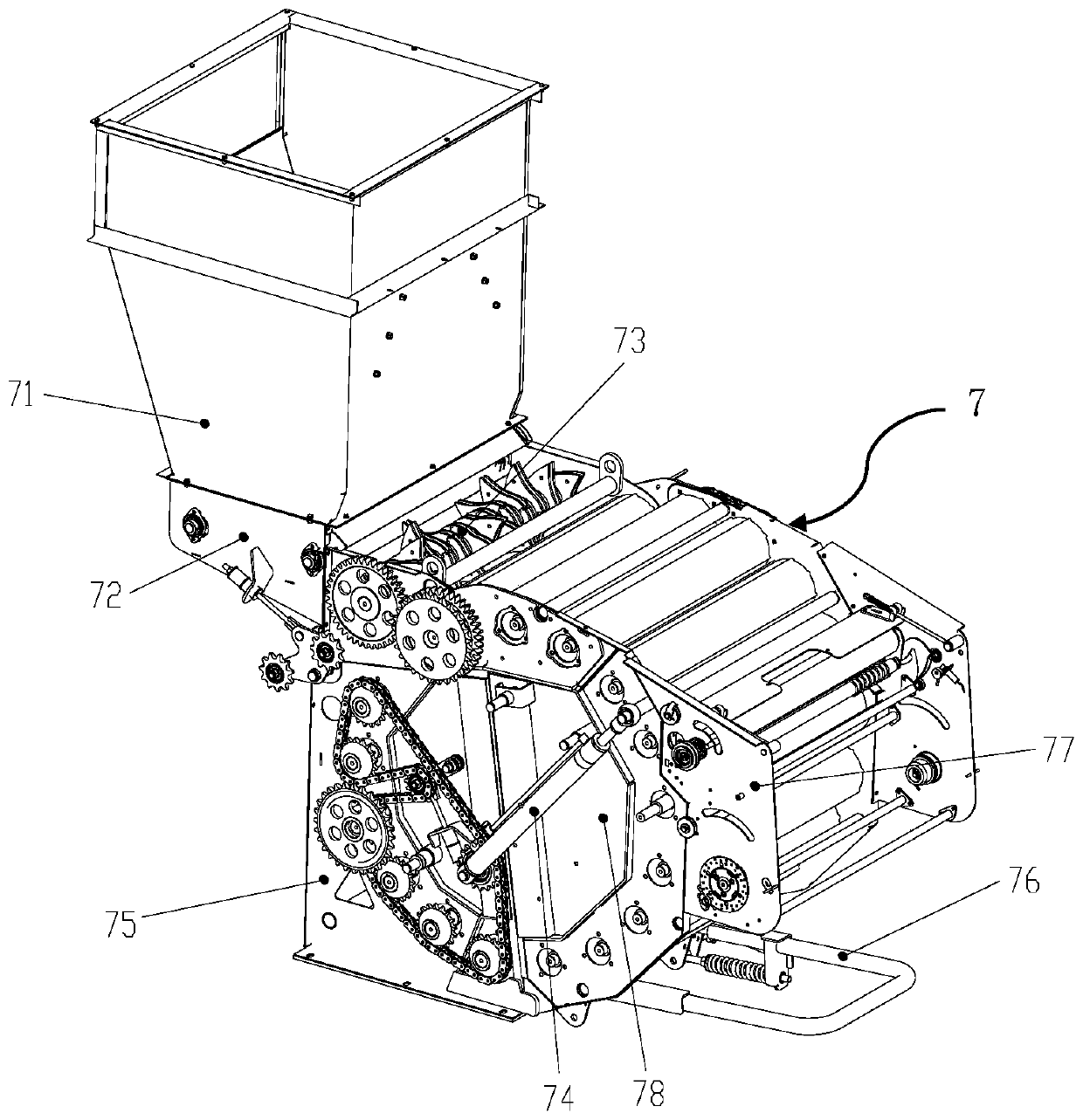
[0078] see figure 1 , figure 1 It is a schematic structural diagram of the whole machine according to an embodiment of the present invention. The self-propelled strapping machine of the present invention comprises a frame 1 and a self-propelled chassis 2 and a power drive 8 mounted on the frame 1, the chassis is located below the frame 1 and is connected to the power The driving device 8 is connected, and also includes a pick-up header 3, a feeding device 4, a crushing device 5, a throwing device 6 and a bundling device 7 installed on the frame 1 and arranged in sequence, and the pick-up header 3 is installed At the front end of the frame 1, the front end of the feeding device 4 is arranged corresponding to the picking header 3 and connected with the picking header 3, and the crushing device 5 is located between the feeding ...


PUM


Abstract

The invention discloses a self-propelled bundling machine. The self-propelled bundling machine comprises a machine frame, a self-propelled chassis and a power driving device; the self-propelled chassis and the power driving device are mounted on the machine frame; the chassis is located below the machine frame and connected with the power driving device; the bundling machine further comprises a picking and cutting table, a feeding device, a crushing device, a throwing device and a bundling device which are mounted on the machine frame and arranged in sequence; the picking and cutting table ismounted at the front end of the machine frame; the front end of the feeding device corresponds to the picking and cutting table; the crushing device is connected with the feeding device and the throwing device; the outlet end of the throwing device is connected with the bundling device; and the power driving device is connected with the picking and cutting table, the feeding device, the crushing device, the throwing device and the bundling device. The bundling machine is suitable for harvesting various crops such as straws and pasture grass, can complete the operation of picking and collecting, feeding, crushing, throwing, soil and impurity removing, bundling and net winding, net cutting and bundle unloading and the like, realizes self-propelled non-stop continuous harvesting and bundling,and improves the efficiency while ensuring the quality.

Description

technical field [0001] The invention relates to an agricultural harvesting machine, in particular to a self-propelled tying machine. Background technique [0002] At present, with the development of environmental protection and comprehensive utilization of biomass, the recycling and reuse of residues after crop harvest has increasingly high requirements for agricultural mechanization. In the prior art, square balers and round balers are mainly used to recycle and reuse the residues after harvesting crops, but both have the problem that the balers cannot work independently and need to be pulled by a tractor. At the same time, the picking mechanism of the baler of the prior art is located below the baling mechanism, and the crop stems after picking up directly enter the baling mechanism for packaging, which easily causes the soil adhered to the crop stalks to fail to be removed during the picking process. It is directly sent to the baling mechanism to be mixed in the bale, an...

Claims


Application Information

Patent Timeline
IPC IPC(8): A01F15/07A01F15/08A01D89/00
CPCA01D89/001A01F15/071A01F15/08
Inventor 刘天舒杨军太徐名汉董世平景全荣陈月锋申文龙黄允魁尹玲玉李杨
Owner CHINESE ACAD OF AGRI MECHANIZATION SCI
Learn More