
Double-resonance type wireless electric energy transmission system and method based on special receiving end coil

A wireless energy transmission and receiving end technology, applied in the direction of electrical components, circuit devices, etc., can solve the problems of low transmission efficiency, small charging range, short transmission distance, etc., achieve high charging power, material and space saving, and meet the requirements of free movement effect of demand

Pending Publication Date: 2020-07-14
SHANGHAI COUPLING INTELLIGENT TECH CO LTD
View PDF0 Cites 1 Cited by
  • Summary
  • Abstract
  • Description
  • Claims
  • Application Information

AI Technical Summary

Problems solved by technology

[0004] In order to solve the problems of short transmission distance, low transmission efficiency and small charging range in the existing wireless power transmission system, the present invention provides a dual-resonance wireless power transmission system and method based on a special receiving coil

Method used


Image

  • Double-resonance type wireless electric energy transmission system and method based on special receiving end coil
  • Double-resonance type wireless electric energy transmission system and method based on special receiving end coil
  • Double-resonance type wireless electric energy transmission system and method based on special receiving end coil

Examples


Embodiment Construction

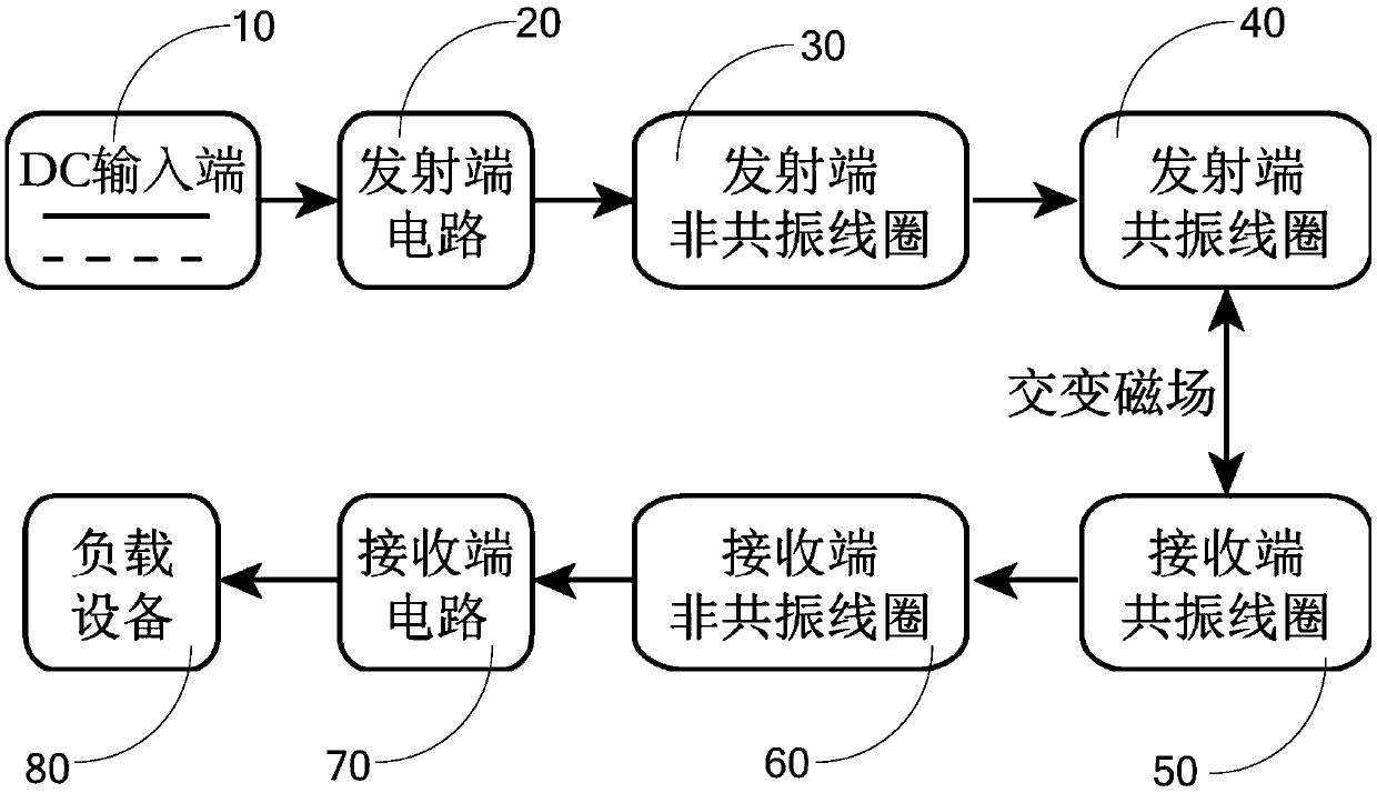
[0035] In order to solve the problems of short transmission distance, low transmission efficiency and small charging range in the existing wireless power transmission system, the present invention provides a dual-resonance wireless power transmission system and method based on a special receiving coil.

[0036] The dual-resonance wireless power transmission system and method based on the special receiver coil of the present invention will be further described below in conjunction with the accompanying drawings and specific embodiments. Those skilled in the art can easily understand other advantages and effects of the present invention from the contents disclosed in this specification.

[0037] combine Figure 1 to Figure 3 As shown, the present invention is based on a dual-resonant wireless power transfer system with a special receiving coil. The receiving end of the system includes a receiving end circuit 70, a receiving end non-resonant coil 60, and a receiving end resonant ...


PUM


Abstract

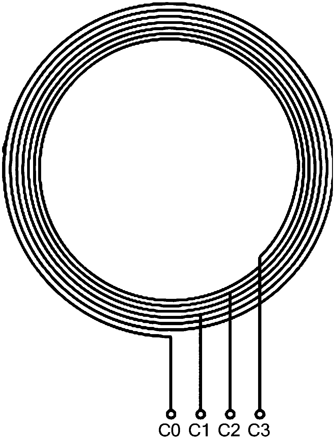
The invention provides a double-resonance type wireless electric energy transmission system and method based on a special receiving end coil, and the receiving end of the double-resonance type wireless electric energy transmission system based on the special receiving end coil comprises a receiving end circuit, a receiving end non-resonance coil, and a receiving end resonance coil. The receiving end non-resonance coil is provided with a main contact, the main contact is electrically connected to the first end of the receiving end circuit, and the receiving end non-resonance coil is further provided with a plurality of auxiliary contacts with the number of turns different from that of the coil between the main contact and the auxiliary contacts; the control module is used for acquiring thedistance between the receiving end and the transmitting end; the switching module is used for adjusting the number of turns of the off-resonance coil of the receiving end according to the distance anda certain rule, the first end of the switching module is electrically connected to the second end of the receiving end circuit, the second end of the switching module is electrically connected to oneauxiliary contact in a switchable mode, and the control end of the switching module is electrically connected to the control module. According to the invention, high-efficiency and free-moving wireless power transmission under a single working frequency is realized.

Description

technical field [0001] The invention relates to the field of wireless power transmission, in particular to a dual-resonance wireless power transmission system and method based on a special receiving coil. Background technique [0002] The development of the wireless power transmission system has gone through several stages. The initial scheme directly generates an alternating electromagnetic field coupling inductive type through a coil. Although this scheme (Qi standard) has been mass-produced, its shortcomings are also very prominent. On the one hand, the transmission distance is very short (not exceeding 10mm), on the other hand, the energy transmission efficiency of this method is not high (less than 50%), which leads to the problem of a small charging range. The magnetic resonance scheme proposed by Professor Marin of the Massachusetts Institute of Technology can effectively increase the energy transmission distance, but its shortcomings are also very obvious. There is o...

Claims


Application Information

Patent Timeline
Patent Type & Authority Applications(China)
IPC IPC(8): H02J50/12
CPCH02J50/12
Inventor 李云辉祝可嘉江俊卢杰吕渴强刘羽何毅辉
Owner SHANGHAI COUPLING INTELLIGENT TECH CO LTD
Learn More