
Optimal design method of variable-rigidity spiral spring

A coil spring and optimized design technology, applied in the field of coil springs, can solve the problem that coil springs cannot meet the load capacity, compression and extension stroke and layout space at the same time, meet the needs of use, ensure driving stability and safety, and simplify processing. The effect of craftsmanship

Active Publication Date: 2020-07-14
BEIJING INST OF SPACE LAUNCH TECH +1
View PDF5 Cites 0 Cited by
  • Summary
  • Abstract
  • Description
  • Claims
  • Application Information

AI Technical Summary

Problems solved by technology

For example, for a super-heavy vehicle with a single axle load of 13t, the load on the coil spring should not be less than 10t. If the wheel runout is -150~150mm, the compression and extension stroke of the coil spring should not be less than -85~85mm; The vertical and lateral layout space that heavy vehicles can provide, the vertical length of the coil spring should not be greater than 700mm, and the outer diameter of the coil spring should not be greater than 210mm. Under the constraints of these conditions, the existing coil spring cannot meet the load capacity at the same time , Compression and expansion stroke and layout space requirements

Method used


Image

  • Optimal design method of variable-rigidity spiral spring
  • Optimal design method of variable-rigidity spiral spring
  • Optimal design method of variable-rigidity spiral spring

Examples


specific Embodiment approach

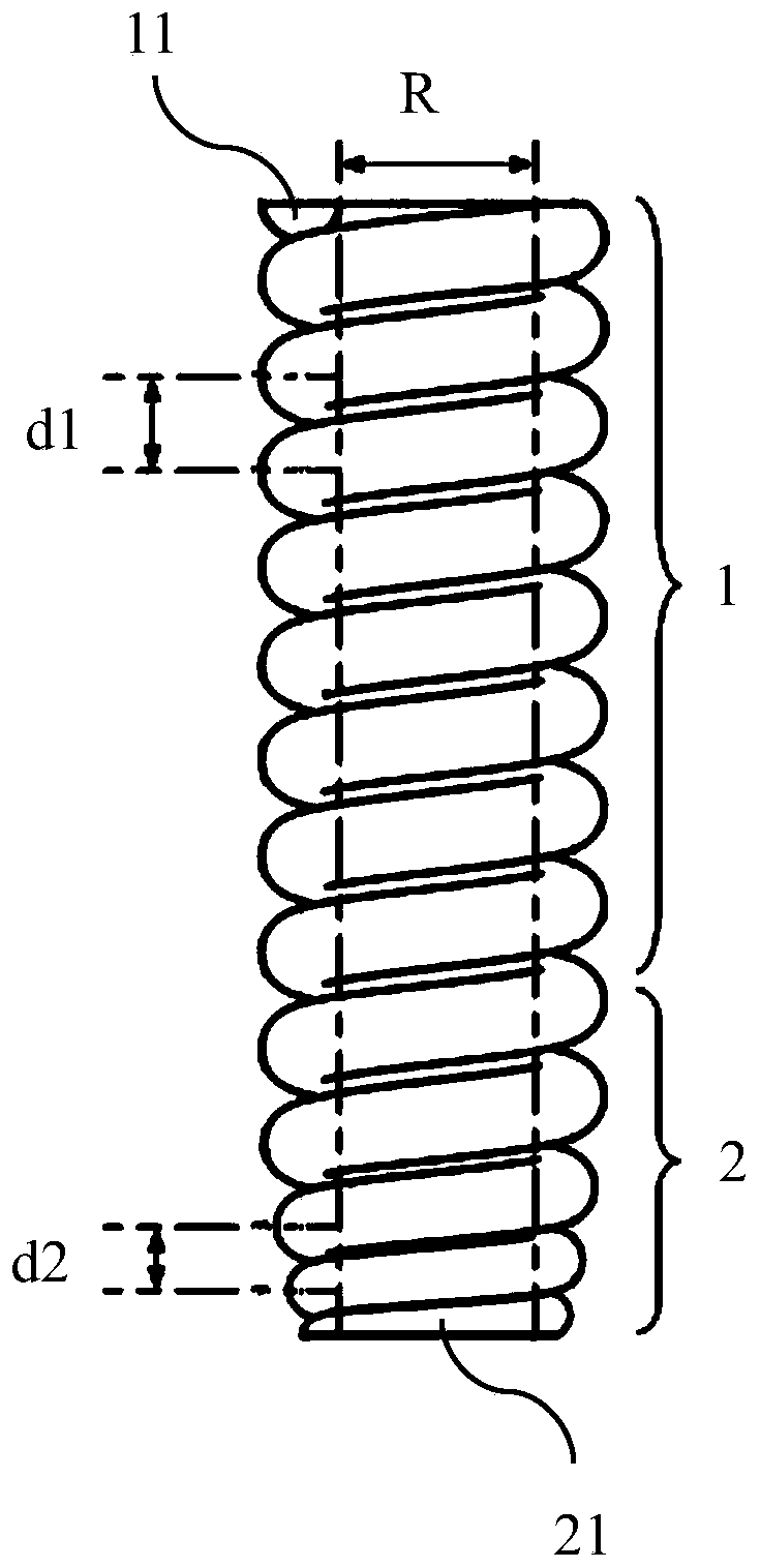
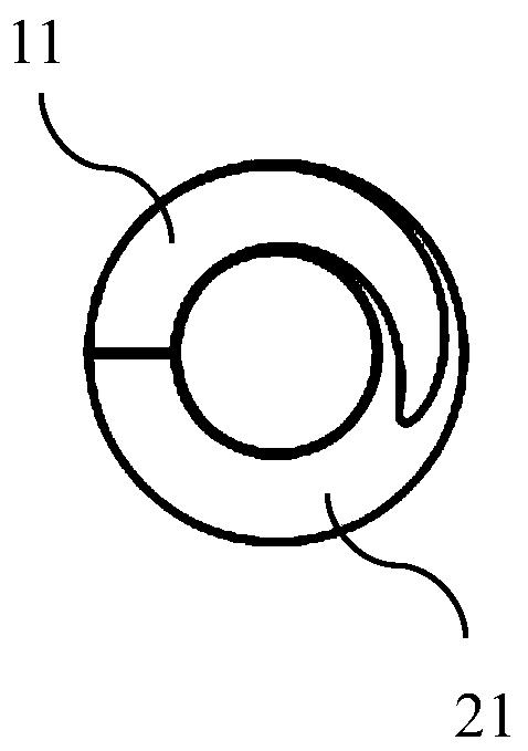
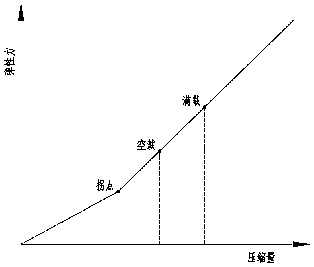
[0031] Such as Figure 1 to Figure 3 Shown is a specific embodiment of an optimal design method for a variable stiffness helical spring of the present invention, comprising the following steps:

[0032] 1. Estimate the initial value of the wire diameter, initial pitch, inner diameter and length of the coil spring according to the required load and compression and extension stroke of the coil spring.

[0033] 2. Input the initial value of wire diameter, initial value of pitch, initial value of inner diameter and initial value of length of the coil spring into the simulation platform, and establish the finite element model of the coil spring.

[0034] 3. Use the finite element analysis method in the simulation platform to analyze the structural stress of the coil spring finite element model to determine its stress level and dangerous point location.

[0035] 4. According to the stress level and dangerous point position of the coil spring finite element model, optimize the wire ...


PUM


Abstract

The invention discloses an optimal design method of a variable stiffness spiral spring. The optimal design method comprises the following steps: estimating a wire diameter initial value, a pitch initial value, an inner diameter initial value and a length initial value of the spiral spring; inputting the initial wire diameter value, the initial pitch value, the initial inner diameter value and theinitial length value of the spiral spring into a simulation platform, and establishing a finite element model of the spiral spring; performing structural stress analysis on the spiral spring finite element model in the simulation platform to determine the stress level and the dangerous point position; optimizing a wire diameter parameter, a pitch parameter, an inner diameter parameter and a lengthparameter of the spiral spring finite element model; and performing a force application simulation test on the spiral spring finite element model, and determining a wire diameter optimization value,a pitch optimization value, an inner diameter optimization value and a length optimization value of the spiral spring finite element model. The designed spiral spring has the advantages of the variable rigidity, the large load, the large stroke, no maintenance and the high reliability, and the compression and extension stroke is increased on the basis of ensuring the bearing capacity.

Description

technical field [0001] The invention relates to a helical spring, in particular to an optimal design method of a variable stiffness helical spring. Background technique [0002] As the elastic element of the vehicle suspension system, the coil spring is installed between the frame and the wheel, and plays an important role in buffering and damping. Coil springs have the advantages of high energy density, low cost, maintenance-free, and high reliability. They are mainly used in passenger cars, but are rarely used in commercial vehicles, especially super-heavy vehicles. Super-heavy vehicles usually adopt a double-wishbone independent suspension system. The double-wishbone independent suspension system has the advantages of large load and large stroke, but its reliability is relatively low and maintenance is troublesome. If a super-heavy vehicle adopts a coil spring suspension system, in order to ensure the bearing capacity of the coil spring, it is necessary to make the diame...

Claims


Application Information

Patent Timeline
Patent Type & Authority Applications(China)
IPC IPC(8): G06F30/17G06F30/23G06F119/14
CPCY02T90/00
Inventor 万芳张军伟吴学雷杨波李洪彪李辰乔杰左霞
Owner BEIJING INST OF SPACE LAUNCH TECH
Learn More