
Distortion generator for testing transient total pressure distortion of axial flow compressor

A generating device and compressor technology, which is applied in the direction of machines/engines, mechanical equipment, non-variable pumps, etc., can solve problems such as the inability of the distortion plate to rotate, the impact, and the interference of the uniform incoming flow field.

Pending Publication Date: 2020-07-14
INST OF ENGINEERING THERMOPHYSICS - CHINESE ACAD OF SCI
View PDF0 Cites 3 Cited by
  • Summary
  • Abstract
  • Description
  • Claims
  • Application Information

AI Technical Summary

Problems solved by technology

Although this kind of experiment method can get the influence of the total pressure loss caused by the crescent-shaped insert plate on the stability of the compressor, it is based on the experiment of the steady-state flow field, that is, it is assumed that there is such a distortion in the inlet, which is different from The actual situation does not match, because the maneuvering actions of the actual aircraft during flight are all completed in a relatively short period of time, so the traditional plug-in experiment fundamentally has this kind of defect, which reduces the actual reference value of the experimental data
[0004] Most of the existing transient distortion devices are designed in the flow channel of the compressor, and gradually change the turbulence angle of the distortion plate to generate a distorted flow field that changes with time. However, since the initial structure of the distortion device is in the flow channel of the compressor, This in itself already disturbs the uniform incoming flow field
Moreover, due to the limitation of relative movement, the distortion plate cannot be rotated to fully fit on the casing wall, so this kind of transient distortion experiment has certain limitations

Method used


Image

  • Distortion generator for testing transient total pressure distortion of axial flow compressor
  • Distortion generator for testing transient total pressure distortion of axial flow compressor
  • Distortion generator for testing transient total pressure distortion of axial flow compressor

Examples


Embodiment Construction

[0056] In order to make the object, technical solution and advantages of the present invention clearer, the present invention will be further described in detail below in conjunction with specific embodiments and with reference to the accompanying drawings.

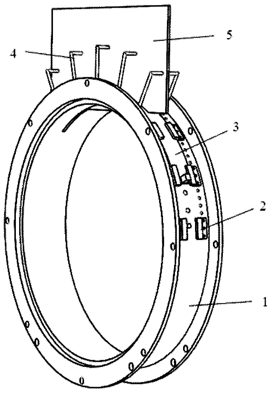
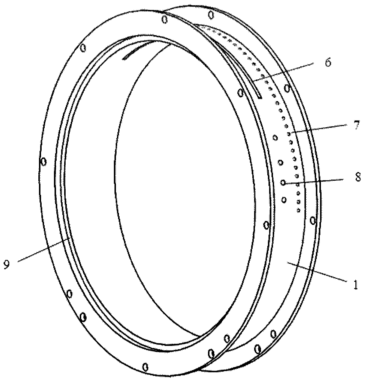
[0057] An embodiment of the present invention provides a distortion generating device for testing the transient total pressure distortion of an axial flow compressor. The structural features of the device include:

[0058] Slotted casing, including an arc-shaped square slot hole arranged in the circumferential direction, a plurality of threaded blind holes arranged on both sides of the arc-shaped square slot hole and parallel to it, and an arc-shaped square slot arranged symmetrically relative to the right-view datum plane Pin positioning holes at both ends of the hole;

[0059] A plurality of slide rail blocks are discretely fixed on some threaded blind holes on both sides of the arc-shaped square groove;

[0060] Two s...


PUM


Abstract

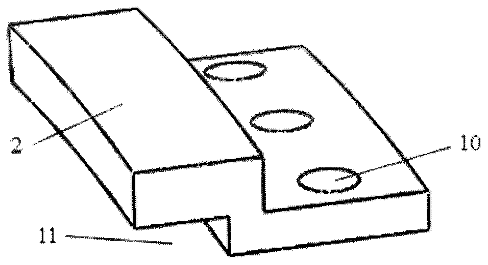
The invention discloses a distortion generator for testing transient total pressure distortion of an axial flow compressor. The distortion generator comprises a slotting power brake, a plurality of sliding rail blocks, two slotting sliding sheets, a plurality of L-shaped feet and a distortion plate, wherein the slotting power-brake comprises an arc square slot hole, a plurality of threaded blind holes and pin positioning holes; the sliding rail blocks are discretely fixed on the partial threaded blind holes at the two sides of an arc-shaped square slot; one sides of the two slotting sliding sheets are provided with arc square slot opening, the two arc square slot openings are partially or fully overlapped on the arc square slot holes, and two slotting sliding sheets are fitted on the surface of the slotting power-gate and move along a track space formed by the sliding rail blocks; each L-shaped foot is spaced from each other and connected with the threaded blind holes; and the distortion plate is erected on a square slot formed by the arc square slot holes and the arc square slot openings, and the distortion plate is balanced and fixed by the L-shaped feet. The distortion generatorprovided by the invention can instantaneously generate transient distortions with different distortion strengths according to the operating conditions of the compressor, so that the experimental datahas more reference significance.

Description

technical field [0001] The invention relates to the technical field of gas turbine / aeroengine, and its significance lies in that it provides an experimental device for simulating the instantaneous non-uniform intake distortion of a real compressor on a modeled low-speed axial flow compressor test bench. Background technique [0002] When the existing aero-engine takes off and lands at a high angle of attack, has a large sideslip, and the military aircraft completes high-mobility tactical actions, the flow separation of the airflow generated by the inlet lip will bring about instantaneous non-uniform total pressure intake distortion, which will affect the engine. Therefore, it is necessary to simulate this situation experimentally to explore its physical effect on stability. [0003] For the simulation experiment of airflow separation at the inlet lip, the existing traditional distortion experiment technology is to design a series of crescent-shaped inserts and test their inf...

Claims


Application Information

Patent Timeline
Patent Type & Authority Applications(China)
IPC IPC(8): F04D27/00
CPCF04D27/001
Inventor 杜娟李益涵李继超刘洋张宏武聂超群
Owner INST OF ENGINEERING THERMOPHYSICS - CHINESE ACAD OF SCI
Learn More