A kind of assembly method of rotating target
An assembly method and a technology of rotating targets, which are applied in auxiliary devices, metal material coating technology, auxiliary welding equipment, etc., can solve problems such as difficult to achieve, low welding pass rate, complicated welding process, etc., and achieve uniform splicing gaps and welded joints High rate, highly consistent results
- Summary
- Abstract
- Description
- Claims
- Application Information
AI Technical Summary
Problems solved by technology
Method used
Image


Examples
Embodiment 1
[0068] In this embodiment, the assembly of the rotating target is carried out according to the following method:
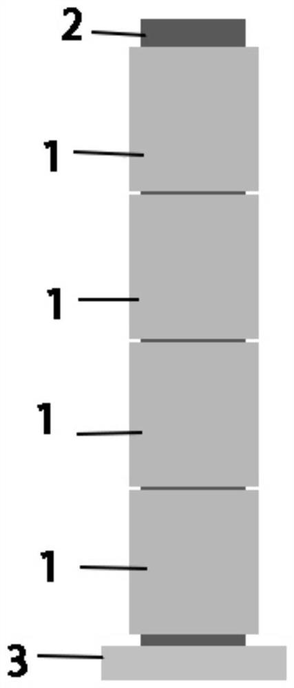
[0069] First, the rotating target 1 (AZO ceramic tube) to be spliced is heated and soaked at 220°C for 40 minutes with indium solder (accompanied by ultrasonic treatment of the surface), and the back tube 2 (stainless steel back tube) is heated and soaked with indium solder at 220°C for 50 minutes. (with ultrasonic treatment of the surface), followed by splicing.
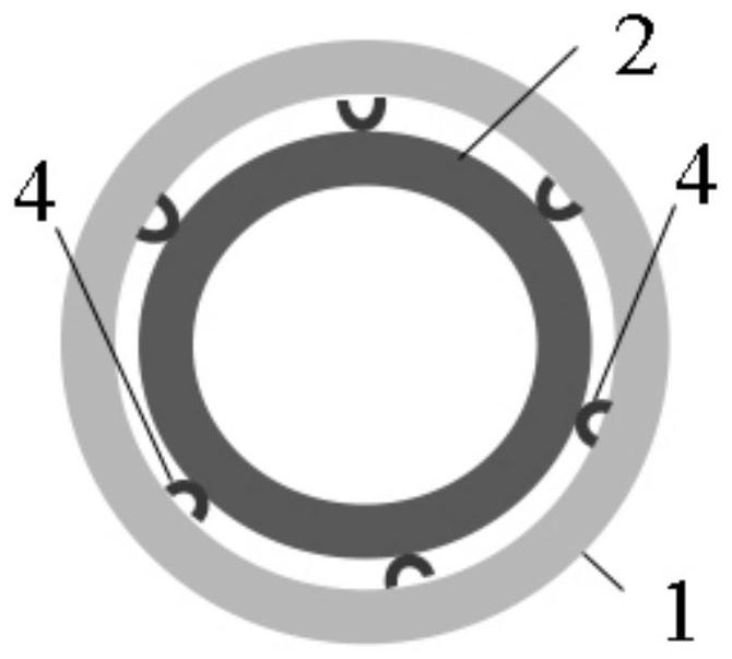
[0070] Press the back tube 2 and the 4 rotating targets 1 into the figure 1 As shown in the splicing, the rotating target 1 is set on the back tube 2, and the back tube 2 is vertically placed on the base 3. The splicing gap is separated by the first support 4 (0.8mm copper wire). The first support The shape of 4 is U-shaped, and the U-shaped arc part is bent and tilted, as shown in Figure 2(a), the first support 4 is completely retained in the upper and lower sections of the rotating target 1, and th...
Embodiment 2
[0075] In this embodiment, the assembly of the rotating target is carried out according to the following method:
[0076] First, the rotating target (AZO ceramic tube) to be spliced is heated and soaked with indium solder at 210°C for 50 minutes (with ultrasonic treatment of the surface), and the back tube (stainless steel back tube) is heated and soaked with indium solder for 55 minutes at 210°C (with ultrasonic treatment of the surface). with ultrasonically treated surface), followed by splicing.
[0077] The back tube and three rotating targets are spliced, the rotating target is set on the back tube, the back tube is placed vertically on the base, and the splicing gap is separated by the first support (0.6mm copper wire). The shape of the support is U-shaped, and the U-shaped arc part is bent and tilted, and the first support is completely retained in the upper and lower sections of the rotating target, and the U-shaped first support is bent and tilted. It is located be...
Embodiment 3
[0082] In this embodiment, the assembly of the rotating target is carried out according to the following method:
[0083] First, the rotating target (AZO ceramic tube) to be spliced is heated and soaked with indium solder at 240°C for 35 minutes (with ultrasonic treatment of the surface), and the back tube (stainless steel back tube) is heated and soaked with indium solder at 240°C for 40 minutes (with ultrasonic treatment surface). with ultrasonically treated surface), followed by splicing.
[0084] Splice the back tube and 6 rotating targets. The rotating target is placed on the back tube. The back tube is placed vertically on the base. The splicing gap is separated by the first support (1mm copper wire). The first support The shape of the piece is U-shaped, and the curved part of the U-shaped part is bent and tilted, and the first support part is all kept in the upper and lower sections of the rotating target, and the curved part of the U-shaped first support part is loca...
PUM
| Property | Measurement | Unit |
|---|---|---|
| diameter | aaaaa | aaaaa |
| electrical resistivity | aaaaa | aaaaa |
Abstract
Description
Claims
Application Information
 - Generate Ideas
- Intellectual Property
- Life Sciences
- Materials
- Tech Scout
- Unparalleled Data Quality
- Higher Quality Content
- 60% Fewer Hallucinations
Browse by: Latest US Patents, China's latest patents, Technical Efficacy Thesaurus, Application Domain, Technology Topic, Popular Technical Reports.
© 2025 PatSnap. All rights reserved.Legal|Privacy policy|Modern Slavery Act Transparency Statement|Sitemap|About US| Contact US: help@patsnap.com