
Industrial waste gas purifier

A technology of industrial waste gas and purifier, applied in the direction of chemical instruments and methods, gas treatment, combined devices, etc., can solve the problems of reducing the overall purification efficiency, affecting the rate of malodorous gas entering the photolysis chamber, and high labor intensity. Convenient centralized disassembly or cleaning, reducing the probability of dust passing through, and the effect of high purification efficiency

Active Publication Date: 2020-07-14
攀枝花市蓝鼎环保科技有限公司
View PDF15 Cites 2 Cited by
  • Summary
  • Abstract
  • Description
  • Claims
  • Application Information

AI Technical Summary

Problems solved by technology

Existing UV photolysis purifiers usually add finer filters at both ends of the intake and exhaust, so that the gas entering the photolysis chamber contains little or no dust and impurities, but over time, the filter will stick Some impurity filter cakes, especially some gases with high dust content, greatly affect the rate of malodorous gases entering the photolysis chamber, thereby reducing the overall purification efficiency. Only by clearing can the flow rate of malodorous gas into the photolysis chamber be large. This method is labor-intensive and easily affects the overall purification efficiency. Therefore, it is necessary to design a stable dust-proof and adjustable The purifier with the flow rate of the solution chamber

Method used


Image

  • Industrial waste gas purifier
  • Industrial waste gas purifier
  • Industrial waste gas purifier

Examples


Embodiment Construction

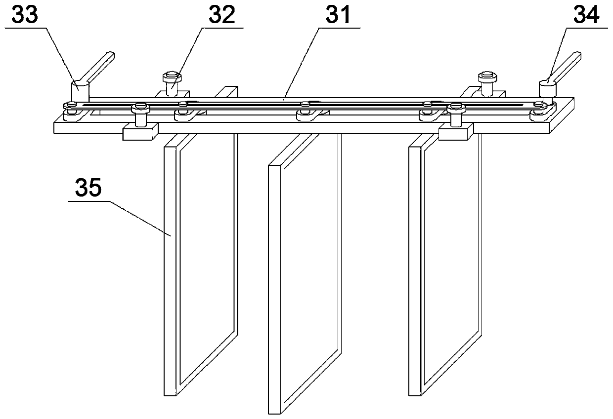
[0022] Such as Figure 1 to Figure 5 As shown, the industrial waste gas purifier provided in this embodiment includes a dust removal chamber 1 and a UV photolysis chamber 2 that are connected to each other. 4. One side of the UV photolysis chamber 2 is provided with an air outlet. This application replaces the current form of installing a fine filter screen at the waste gas inlet 4 and the air outlet. The dustproof assembly 3, the dustproof assembly 3 includes a fixed base 31 and a plurality of dust shields 35 arranged side by side and parallel to each other, the fixed base 31 includes a seat plate 311 and two fixing pieces respectively fixed on both sides of the seat plate 311 32. Each fixing piece 32 is connected to the top wall of the dust removal chamber 1. The fixing piece 32 includes a seat body 321, a screw rod 322 and a nut 323. The seat body 321 is fixed on the side wall of the seat plate 311, and the screw rod 322 is vertically fixed on the seat plate. body 321, and...


PUM


Abstract

The invention discloses an industrial waste gas purifier which comprises a dust removal chamber and a UV photolysis chamber, a dustproof assembly is mounted in the dust removal chamber; the dustproofassembly comprises a fixed seat and a plurality of dust baffles which are arranged in parallel and are parallel to one another; the fixing base comprises a base plate and a plurality of fixing piecesfixed to the two sides of the base plate. Each fixing piece is connected with the top wall of the dust removal chamber; the base plate is horizontally mounted on the lower surface of the top wall of the inner cavity of the dust removal chamber through the plurality of fixing pieces; the length direction of the seat plate is consistent with the waste gas trend of the dust removal chamber; wherein the plurality of dust baffles are movably connected to the lower surface of the base plate, the plurality of dust baffles are divided into a plurality of left dust baffles and a plurality of right dustbaffles, the seat plate is provided with a rotation control assembly used for enabling all the dust baffles to simultaneously rotate, and the seat plate is also provided with an adjustment control assembly used for simultaneously adjusting the distance between the adjacent dust baffles. The purifier can stably prevent dust and adjust the purification of the flow of malodorous gas entering the photolysis chamber.

Description

technical field [0001] The invention relates to the technical field of industrial waste gas purification, in particular to an industrial waste gas purifier. Background technique [0002] At present, UV photolysis purifiers have been widely used in various occasions that require environmental protection and purification. It is a device that uses a special high-energy and high-ozone UV ultraviolet light beam to irradiate odorous gases and crack the odorous gases. Existing UV photolysis purifiers usually add finer filters at both ends of the intake and exhaust, so that the gas entering the photolysis chamber contains little or no dust and impurities, but over time, the filter will stick Some impurity filter cakes, especially some gases with high dust content, greatly affect the rate of malodorous gases entering the photolysis chamber, thereby reducing the overall purification efficiency. Only by clearing can the flow rate of malodorous gas into the photolysis chamber be large....

Claims


Application Information

Patent Timeline
IPC IPC(8): B01D50/00B01D53/00
CPCB01D53/007B01D2257/90B01D50/20
Inventor 唐刚曾景祥李富勇徐筠黄安军黄明忠曾中东
Owner 攀枝花市蓝鼎环保科技有限公司
Learn More