
A multi-station winding device

A winding device and multi-station technology, applied in the direction of battery assembly, sustainable manufacturing/processing, climate sustainability, etc., can solve the problems affecting the continuity of the whole machine operation, unstable transmission, low work efficiency, etc. Achieve the effects of simple structure, good operation continuity and improved work efficiency

Active Publication Date: 2022-04-01
SUZHOU JIERUISI INTELLIGENT TECH CO LTD
View PDF10 Cites 0 Cited by
  • Summary
  • Abstract
  • Description
  • Claims
  • Application Information

AI Technical Summary

Problems solved by technology

Therefore, due to the need to simultaneously drive a plurality of winding needles to rotate and change stations and to drive a single winding needle to rotate and move axially, the current multi-station winding devices generally have complex structures, large volumes, and large losses. The force point of the needle is at the other end of the needle needle relative to the needle nozzle, and the transmission is unstable, which will affect the continuity of the whole machine operation and lower work efficiency

Method used


Image

  • A multi-station winding device
  • A multi-station winding device
  • A multi-station winding device

Examples


Embodiment Construction

[0030] The following will clearly and completely describe the technical solutions in the embodiments of the present invention with reference to the accompanying drawings in the embodiments of the present invention. Obviously, the described embodiments are only some, not all, embodiments of the present invention.

[0031] Examples of the described embodiments are shown in the drawings, wherein like or similar reference numerals designate like or similar elements or elements having the same or similar functions throughout. The embodiments described below by referring to the figures are exemplary and are intended to explain the present invention and should not be construed as limiting the present invention.

[0032] In describing the present invention, it should be understood that the terms "center", "longitudinal", "transverse", "length", "width", "thickness", "upper", "lower", "front", " Back", "Left", "Right", "Vertical", "Horizontal", "Top", "Bottom", "Inner", "Outer", "Clock...


PUM


Abstract

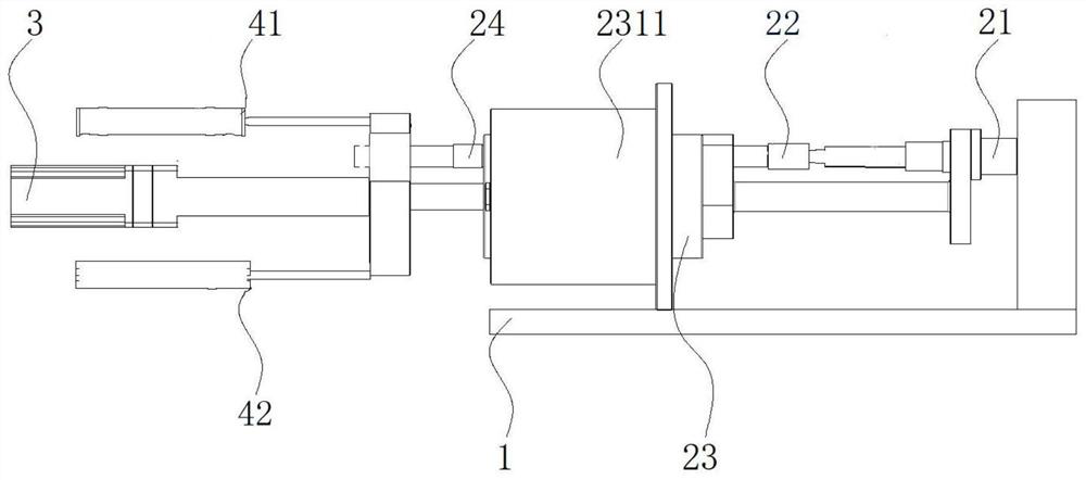
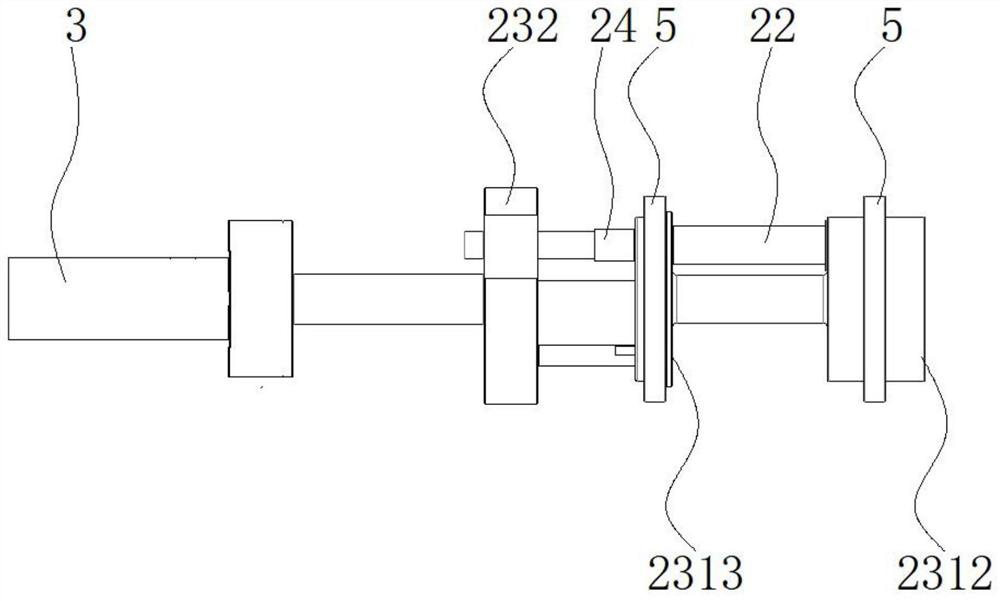
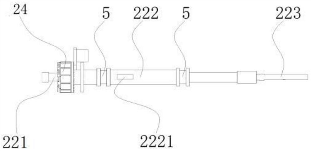
The invention discloses a multi-station winding device, which comprises a base; a winding mechanism is connected with a transposition driving assembly and drives the winding mechanism to revolve through the transposition driving assembly; the winding mechanism includes a front needle nozzle, a plurality of coils Needle assembly and multiple sets of driving sources, multiple sets of driving sources correspondingly drive multiple sets of needle winding assemblies to rotate; a single set of needle winding assembly includes needle winding, needle winding handle and shaft sleeve, and the driving source is directly connected to the winding needle handle or shaft sleeve to drive the winding needle The needle rotates by itself, and the needle winding handle can move axially in the shaft sleeve. Driven by the needle threading and pulling mechanism, the needle winding handle and the needle winding handle move axially along the shaft sleeve to realize the forward or backward movement. The invention is simple in structure and small in size. The direct drive motor is directly connected to the needle handle or shaft sleeve to directly drive the needle to rotate, which saves the complicated transmission mechanism and has no indirect loss. It can ensure the concentricity and effectively control the winding speed of the equipment. and winding tension, transfer the force point of the needle rotation to the shaft sleeve, so that the force point of the rotation is centered, the transmission is stable, and the continuity of the whole machine is good.

Description

technical field [0001] The invention relates to an automatic winding device, in particular to a multi-station winding device. Background technique [0002] In the production process of lithium battery cells, the positive electrode sheet, the negative electrode sheet, and the separator interposed between them for insulation are wound by a winding device to form a cell. The manufacturing process includes winding, gluing, and blanking. and other processes can be carried out on the winding station, gluing station and unloading station of the winding device respectively. The winding device in the prior art is rotated by a winding needle to wind a battery core. In order to improve the winding efficiency, a double-needle or three-needle winding structure has appeared. The three winding needles are vertically arranged on the follow-up disk, and the three winding needles work in turn: after a certain winding needle is wound, it is driven by the follow-up disk. A winding needle ente...

Claims


Application Information

Patent Timeline
Patent Type & Authority Patents(China)
IPC IPC(8): H01M10/0587H01M10/04
CPCH01M10/0587H01M10/0409Y02E60/10Y02P70/50
Inventor 万志永邱毅王盼
Owner SUZHOU JIERUISI INTELLIGENT TECH CO LTD
Learn More