
Relay drive circuit

A technology for driving circuits and relays, applied in relays, circuits, electrical components, etc., can solve the problems of slower voltage rise, increased power loss of MOS tubes, affecting the service life of MOS tubes, etc., so as to improve service life and reduce power loss. Effect

Active Publication Date: 2022-02-15
XIAMEN HUALIAN ELECTRONICS CO LTD
View PDF8 Cites 0 Cited by
  • Summary
  • Abstract
  • Description
  • Claims
  • Application Information

AI Technical Summary

Problems solved by technology

[0002] In related technologies, the relay excitation circuit usually uses an ordinary RC timing circuit to drive the switch. Due to the charging and discharging characteristics of the capacitor, when the capacitor is about to be fully charged, the voltage rise rate becomes slower, so that after the capacitor is charged for a certain period of time, the voltage across the resistor drops. The speed becomes slow, which greatly increases the turn-off time of the MOS tube, which increases the power loss of the MOS tube during the turn-off process, thus affecting the service life of the MOS tube

Method used


Image

  • Relay drive circuit

Examples


Embodiment Construction

[0017] Embodiments of the present invention are described in detail below, examples of which are shown in the drawings, wherein the same or similar reference numerals designate the same or similar elements or elements having the same or similar functions throughout. The embodiments described below by referring to the figures are exemplary and are intended to explain the present invention and should not be construed as limiting the present invention.

[0018] The main loss of the MOS tube in the working process is the loss of the turn-on process, the loss of the working process and the loss of the turn-off process. The existing low-cost relay excitation circuit mainly uses an ordinary RC timing circuit to drive the switch. The RC timing circuit mainly includes resistors, capacitors and MOS tube; the loss of this circuit in the turn-on process is very small and can be ignored, but due to the charging and discharging characteristics of the capacitor, its turn-off time is long, res...


PUM


Abstract

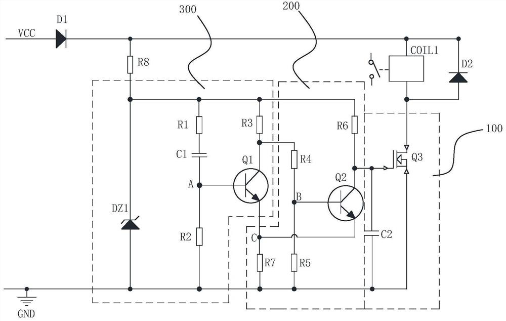
The invention discloses a driving circuit of a relay, the relay includes an exciting coil and a holding coil, the driving circuit includes: a driving unit, a timing switch unit and a positive feedback unit, the driving unit is connected with the exciting coil, the The drive unit is used to drive the excitation coil to be powered on or off; the timing switch unit is connected to the positive feedback unit, the positive feedback unit is connected to the drive unit, and the timing switch unit is turned on when powered on Turning off the positive feedback unit so as to control the drive unit to work, the positive feedback unit starts to conduct when the timing switch unit is turned on and in the amplification region, so that the timing switch unit is turned off , so as to control the driving unit to stop working quickly, thereby reducing the power loss of the MOS tube and increasing its service life.

Description

technical field [0001] The invention relates to the technical field of circuit design, in particular to a driving circuit of a relay. Background technique [0002] In related technologies, the relay excitation circuit usually uses an ordinary RC timing circuit to drive the switch. Due to the charging and discharging characteristics of the capacitor, when the capacitor is about to be fully charged, the voltage rise rate becomes slower, so that after the capacitor is charged for a certain period of time, the voltage across the resistor drops. The speed becomes slow, which greatly increases the turn-off time of the MOS tube, which increases the power loss of the MOS tube during the turn-off process, thereby affecting the service life of the MOS tube. Contents of the invention [0003] The present invention aims to solve one of the technical problems in the above-mentioned technologies at least to a certain extent. For this reason, the object of the present invention is to pr...

Claims


Application Information

Patent Timeline
Patent Type & Authority Patents(China)
IPC IPC(8): H01H47/32
CPCH01H47/32
Inventor 吴文勇钟天禄张志军陈虢林帆
Owner XIAMEN HUALIAN ELECTRONICS CO LTD
Learn More