
Display module with reflection structure and manufacturing method thereof

A display module and reflective structure technology, applied in nonlinear optics, instruments, optics, etc., can solve the problems of dark reflective brightness and low color saturation, and achieve enhanced reflective brightness, enhanced color saturation, and improved pressure resistance Effect

Pending Publication Date: 2020-07-10
WUXI VISION PEAK TECH
View PDF3 Cites 2 Cited by
  • Summary
  • Abstract
  • Description
  • Claims
  • Application Information

AI Technical Summary

Problems solved by technology

[0003] Display screens in the related art include microcup type and microcapsule type, which have relatively dark reflection brightness and low color saturation

Method used


Image

  • Display module with reflection structure and manufacturing method thereof
  • Display module with reflection structure and manufacturing method thereof
  • Display module with reflection structure and manufacturing method thereof

Examples


Embodiment 1

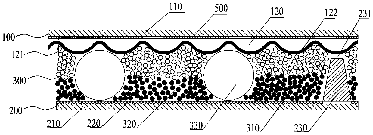
[0055] The first step: provide the lower substrate assembly 200 formed with the plasma barrier weir 230, place the lower substrate assembly 200 formed with the plasma barrier weir 230 on the dispensing platform, and dispense glue on the edge of the upper surface of the lower substrate assembly 200 to form a seal Plastic frame 400.

[0056] The lower substrate assembly 200 includes a lower panel 210 and a pixel electrode 220 formed on the lower panel 210; for example, the lower substrate assembly 200 is a TFT glass substrate, and the material of the lower panel 210 may be transparent glass.

[0057] Step 2: Provide an upper panel 110 , and fabricate a reflective layer 120 on the lower surface of the upper panel 110 to form an upper substrate assembly 100 .

[0058] Exemplarily, the surface of the reflective layer 120 includes a plurality of arc surfaces, the reflective layer 120 can reflect light incident from the direction of the upper panel 110, the upper substrate assembly 1...

Embodiment 2

[0068] Step 1: Provide an upper panel 110 , and fabricate a reflective layer 120 on the lower surface of the upper panel 110 to form an upper substrate assembly 100 .

[0069] Exemplarily, the surface of the reflective layer 120 includes a plurality of arc surfaces, the reflective layer 120 can reflect light incident from the direction of the upper panel 110, the upper substrate assembly 100 is transparent, and the material of the upper panel 110 is transparent The material of the reflective layer 120 can be optical-grade acrylic resin, transparent polymer, transparent inorganic matter, transparent composite material and other materials, which have good reflection effect, and the optical-grade acrylic resin can increase the reflective brightness by 30%. and color saturation.

[0070] Step 2: Dispensing glue on the edge of the surface of the reflective layer 120 to form the sealing frame 400 .

[0071] Exemplarily, the upper substrate assembly 100 is placed on a dispensing pla...


PUM

PropertyMeasurementUnit
heightaaaaaaaaaa
diameteraaaaaaaaaa
diameteraaaaaaaaaa

Abstract

The invention relates to the field of electronic display, in particular to a display module with a reflection structure and a manufacturing method thereof. The display module comprises an upper substrate assembly and a lower substrate assembly, wherein the upper substrate assembly comprises an upper panel and a reflecting layer formed below the upper panel; the lower substrate assembly comprises alower panel and a pixel electrode formed on the lower panel; a display cavity is formed between the upper substrate assembly and the lower substrate assembly, the display cavity is filled with display plasma, and the display plasma can make contact with the reflecting layer and the pixel electrode; the surface, making contact with the display plasma, of the reflecting layer comprises a pluralityof cambered surfaces, and the cambered surfaces protrude towards the display plasma and can reflect incident light from the upper panel. The manufacturing method is used for manufacturing the displaymodule. According to the display module with the reflection structure and the manufacturing method thereof, the reflection brightness of the screen can be further enhanced, the color saturation is enhanced, the anti-reflection effect is achieved, and the pressure resistance of the display screen is improved.

Description

technical field [0001] The present application relates to the field of electronic display, in particular to a display module with a reflective structure and a manufacturing method thereof. Background technique [0002] Electrophoretic display technology uses charged colloids to move under the action of an electric field, and the electrophoretic particles with different photoelectric properties are driven by the electric field to realize the display of images and text. Compared with other known display technologies, the electrophoretic ink display has the following characteristics: flexible and easy to bend, light in weight, thin in thickness, high in contrast, low in energy consumption, wide in viewing angle, readable in sunlight, with image bistable state, easy to Features such as large-scale production. [0003] The display screens in the related art include microcup type and microcapsule type, which have relatively dark reflection brightness and low color saturation. C...

Claims


Application Information

Patent Timeline
Patent Type & Authority Applications(China)
IPC IPC(8): G02F1/16755G02F1/1677G02F1/1679
CPCG02F1/16755G02F1/1677G02F1/1679
Inventor 包进陈山杨扬唐振兴许俊
Owner WUXI VISION PEAK TECH
Learn More