
Liquid crystal display device

a display device and liquid crystal technology, applied in the field of liquid crystal display devices, can solve the problems of difficult to reduce power consumption, display looks dark, and reduce viewability, so as to reduce the size of thin film transistors per pixel, reduce the size of reflection regions and reflectance, and ensure the transmission display. the effect of sufficient illumination

Inactive Publication Date: 2014-01-14
JAPAN DISPLAY WEST
View PDF26 Cites 2 Cited by
  • Summary
  • Abstract
  • Description
  • Claims
  • Application Information

AI Technical Summary

Benefits of technology

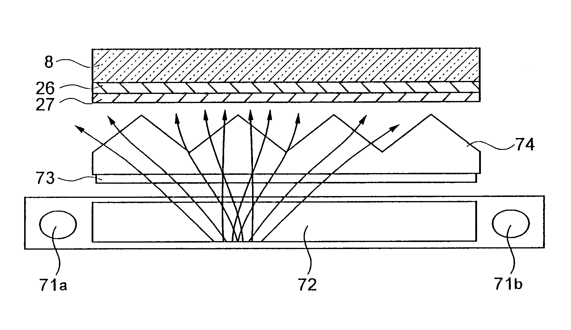
The present invention provides a liquid crystal display device that can handle high-fine display and secure luminance in transmission type display without compromising the minimum requirement for luminance in reflection type display. Specifically, the transmittance is set to be 4% at minimum. By using low temperature polycrystalline silicon, a size of a thin film transistor per pixel is decreased, and the reflection region and reflectance are improved. Additionally, a reflection film with high reflectance or a flat reflection film is formed to further enhance the reflection luminance.

Problems solved by technology

In the transmission type liquid crystal display devices, 50% or more of the total power consumption is taken by the backlight and it is difficult to reduce the power consumption.
Also, the transmission type display devices have a disadvantage that the display looks dark when an ambient light is bright and the viewability is lowered.
On the other hand, in the reflection type liquid crystal display devices, there is no problem of an increase of a power consumption since a backlight is not provided, but there is a disadvantage that the viewability is extremely lowered when an ambient light is low.
In a conventional dual reflection and transmission type liquid crystal display device, however, while it was supposed that both of the transmission type display and the reflection type display were provided together, there have been disadvantages that the luminance was insufficient and the viewability was low when comparing with a normal reflection type and a normal transmission type liquid crystal display devices.
Also, since the minimum size of the window is not regulated, the reflection region cannot be minimized when the transmission type displaying is the main display means.
Concerning an increase in definition to 200 ppi, there has been disadvantages of a decrease of a region able to be used for transmission type display and a decrease of luminance in transmission type display in each pixel, such that minimum widths or pitch of signal lines and gate lines are 5 μm or more due to restrictions of designing a liquid crystal pixel.
However, as explained above, by increasing luminance of the backlight, a power consumption of the liquid crystal display device increases, which becomes a disadvantage for the liquid crystal display device featuring a low power consumption.

Method used


Image

  • Liquid crystal display device
  • Liquid crystal display device
  • Liquid crystal display device

Examples


Embodiment Construction

[0052]Below, embodiments of a liquid crystal display device of the present invention will be explained with reference to the attached drawings.

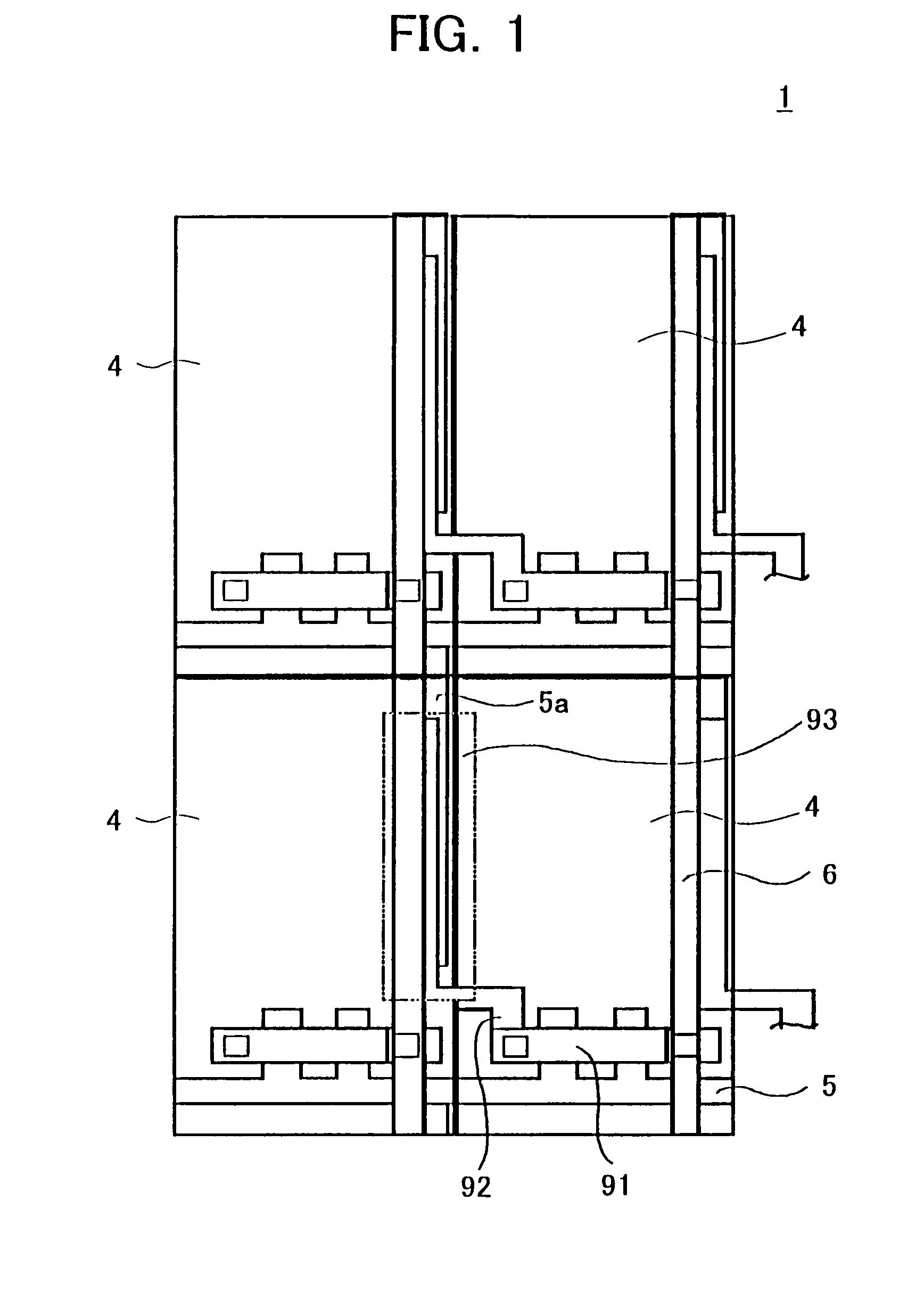
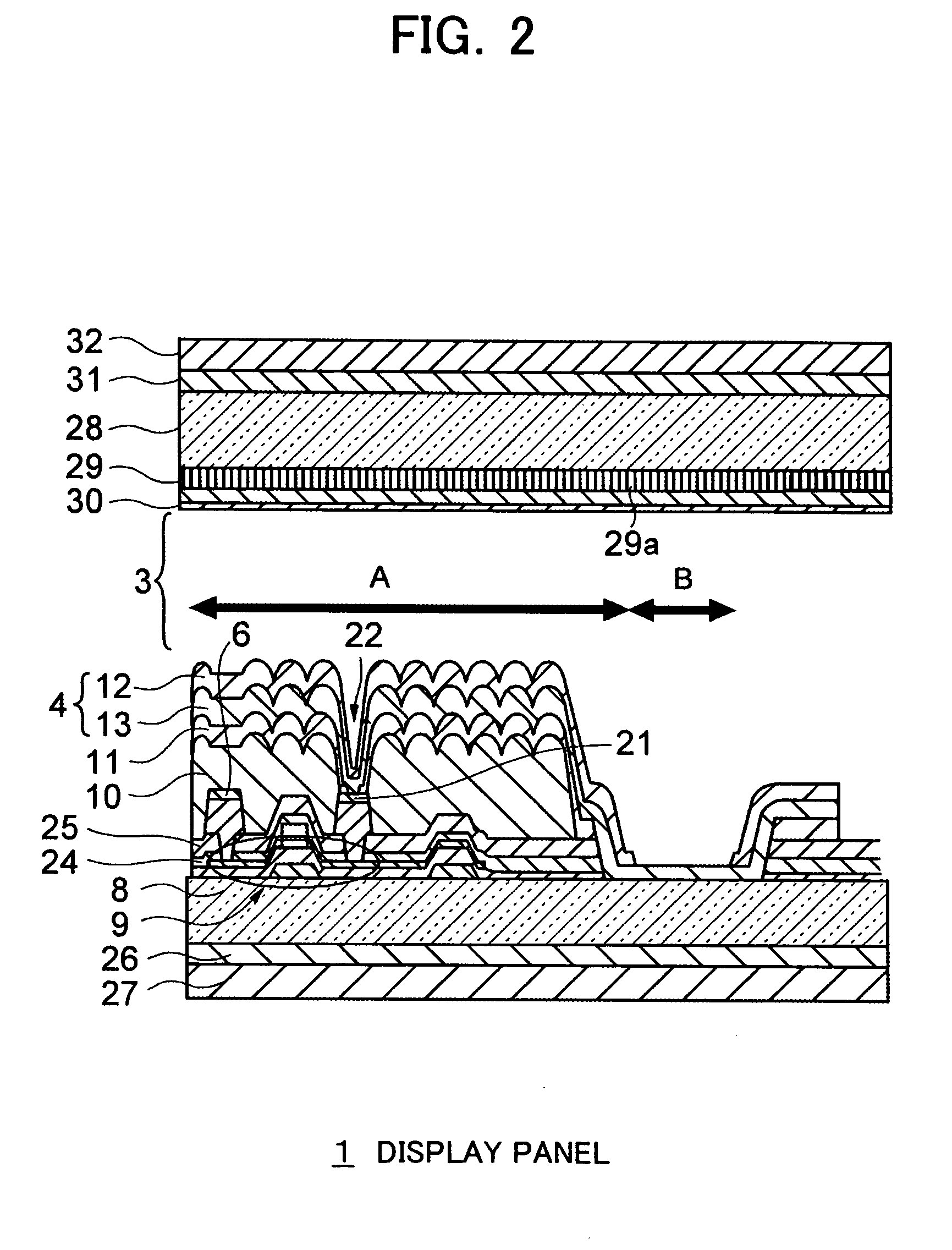
[0053]FIG. 1 is a plan view of a part of a pixel region of a display panel 1 in a liquid crystal display device of the present embodiment, and FIG. 2 shows the sectional configuration of a pixel portion in FIG. 1.

[0054]As shown in FIG. 2, the display panel 1 comprises a transparent insulating substrate 8, a thin film transistor (TFT) 9 formed thereon, and pixel regions 4, etc., and a transparent insulating substrate 28, an overcoat layer 29 formed thereon, a color filter 29a and a counter electrode 30 arranged to face the above first three, and a liquid crystal layer 3 sandwiched by the pixel region 4 and the counter electrode 30.

[0055]As shown in FIG. 1, the pixel portion is configured by the pixel regions 4 arranged in matrix, and gate lines 5 for supplying a scanning signal to the TFT 9 and signal lines 6 for supplying a display signal to ...


PUM

PropertyMeasurementUnit
transmittanceaaaaaaaaaa
reflectanceaaaaaaaaaa

Abstract

A liquid crystal display device capable of dealing with highly definition display and securing both of transmission type display luminance and reflection type display luminance, wherein the Cs on-gate structure is adopted, and a light reflectance is set to be in a range of 1% or more and 30% or less and a light transmittance is set to be in a range of 4% or more and 10% or less on the display panel formed by arranging in matrix a plurality of pixel regions 4 having a reflection region A for reflection type display by reflection of an ambient light and a transmission region B for transmission type display by transmission of light from a light source provided inside.

Description

[0001]This application claims priority to Japanese Patent Application Number JP2002-036416, filed Feb. 14, 2002, which is incorporated herein by reference.[0002]1. Technical Field[0003]The present invention relates to a liquid crystal display device, particularly relates to a liquid crystal display device using both of a reflection type display and a transmission type display.[0004]2. Background Art[0005]By utilizing the characteristics of having a thin shape and a lower power consumption, liquid crystal display devices are used as display devices of a wide range of electronic apparatuses. There are electronic apparatuses using a liquid crystal display device of, for example, notebook type personal computers, displays for car navigation, personal digital assistants (PDAs), mobile phones, digital cameras and video cameras, etc. When roughly dividing these liquid crystal display devices, there are known transmission type liquid crystal display devices for displaying by controlling the...

Claims


Application Information

Patent Timeline
Patent Type & Authority Patents(United States)
IPC IPC(8): G09G3/36G02F1/1335G02F1/1362
CPCG09G3/3614G09G3/3674G09G2310/06G02F1/136213G02F2202/104G09G2330/021G09G3/3648G09G3/3685G02F1/133555G02F1/136
Inventor INO, MASUMITSUTANAKA, TSUTOMUFUKUNAGA, YOKOYAMAGUCHI, HIDEMASANAKAMURA, SHINJI
Owner JAPAN DISPLAY WEST
Learn More