
Liquid crystal display and electronic device

A liquid crystal display and liquid crystal technology, applied in the direction of instruments, optics, nonlinear optics, etc., can solve the problems of blurred display, slow response speed, short service life, etc., and achieve the effect of high response speed, high contrast and high resolution

Pending Publication Date: 2019-10-08
MULTEK DISPLAY
View PDF0 Cites 2 Cited by
  • Summary
  • Abstract
  • Description
  • Claims
  • Application Information

AI Technical Summary

Problems solved by technology

[0003] Electronic paper technology is electrophoretic display. Its principle is to drive the particles with dyes in the microcapsules by an external electric field, which are positively charged white dye particles and negatively charged black dye particles, so as to realize black and white display. This technology The main problem is that the response speed is slow, the operating temperature range is only limited to 0-50 degrees Celsius, it cannot withstand high temperature and high humidity environment, and the service life is short
[0004] Low-power outdoor total reflection LCD technology is to make a layer of internal reflection layer on the traditional AM-TFT array backplane, with optical films such as scattering film and phase difference compensation film, to manufacture a total reflection LCD display without backlight, but The controller of this technology still needs to constantly scan and refresh to maintain the display state, and maintaining the same display screen for a long time will cause problems such as display blur and afterimage, resulting in reduced service life, which is not yet a true ultra-low power consumption and environmental protection LCD Monitor

Method used


Image

  • Liquid crystal display and electronic device

Examples


Embodiment Construction

[0027] The principles and features of the present invention are described below in conjunction with the accompanying drawings, and the examples given are only used to explain the present invention, and are not intended to limit the scope of the present invention.

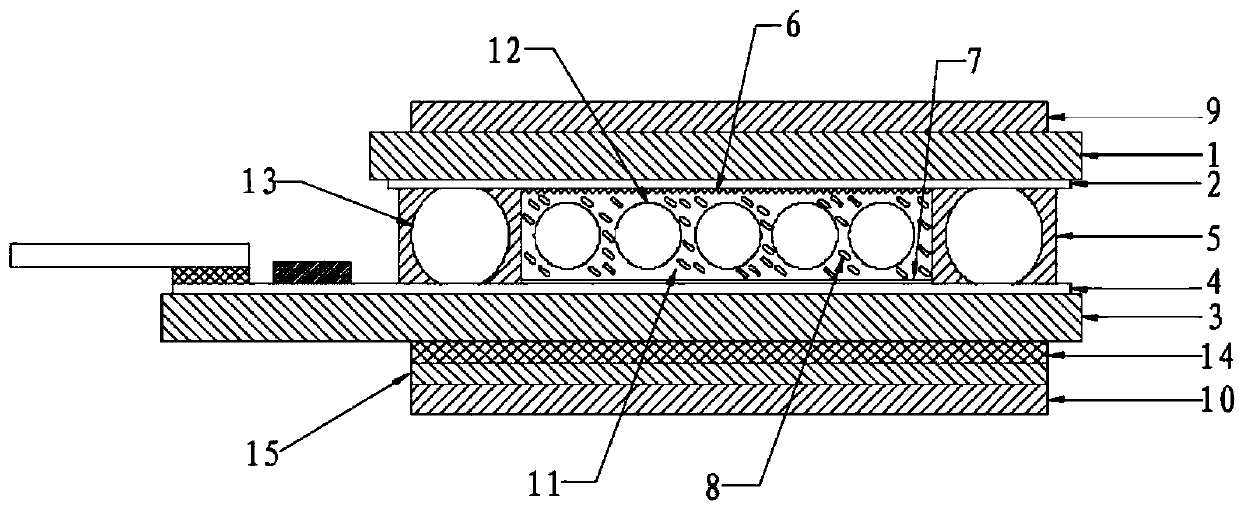
[0028] like figure 1 As shown, a liquid crystal display provided by an embodiment of the present invention includes a first glass substrate 1; a first transparent electrode layer 2; an AM-TFT substrate, and the AM-TFT substrate includes a second glass substrate 3 and a second transparent electrode Layer 4, the second transparent electrode layer 4 includes pixel electrodes and AM-TFT; sealing frame 5; vertical alignment layer 6; parallel alignment layer 7; liquid crystal 8; first polarizer 9 and second polarizer 10 ; The first glass substrate 1 and the second glass substrate 3 are spaced up and down, and the first transparent electrode layer 2 is arranged on the side of the first glass substrate 1 facing the second g...


PUM


Abstract

The invention relates to a liquid crystal display comprising two glass substrates, two transparent electrode layers, and an AM-TFT substrate including the second glass substrate and the second transparent electrode layer, wherein the second transparent electrode layer includes a pixel electrode and an AM-TFT, and the AM-TFT is disposed on the second glass substrate and connected to the pixel electrode; the first and second glass substrates are spaced apart up and down; the first and second transparent electrodes are oppositely disposed between the first and second glass substrates; a molding frame is arranged around the first and second transparent electrodes; a sealing cavity is formed between the molding frame and the first and second transparent electrodes; a vertical alignment orientation layer is disposed on the first transparent electrode layer and in a serrated or wavy shape; a parallel alignment orientation layer is disposed on the second transparent electrode layer; liquid crystal is filled in the sealing cavity; and the two polarizers are respectively disposed on the outer sides of the first and second glass substrates. The product provided by the invention can realize high resolution, high contrast, fast response speed, low power consumption, high temperature and high humidity environment resistance, basically no electricity when maintaining information display, andonly power consumption when refreshing display content.

Description

technical field [0001] The invention belongs to the technical field of liquid crystal displays, and in particular relates to a liquid crystal display and electronic equipment. Background technique [0002] The current mainstream AM-TFT (active matrix thin film transistor) liquid crystal display needs to drive LED backlight, AM-OLED needs to drive organic light-emitting materials, the display device consumes a lot of power, and requires the controller to continuously scan and refresh to maintain the display state, and Keeping the same display screen for a long time will lead to problems such as display blurring and afterimages, and the service life will be greatly reduced, and there will be problems such as insufficient brightness, poor visual effect or high power consumption and low reliability under strong sunlight. , not suitable for outdoor display and low power consumption display field, in addition, the AC drive of the backlight and the display constantly scan and refre...

Claims


Application Information

Patent Timeline
IPC IPC(8): G02F1/1337G02F1/1339G02F1/1335G02F1/139
CPCG02F1/133723G02F1/133753G02F1/133528G02F1/13392G02F1/1339G02F1/133504G02F1/1391G02F1/133531G02F1/133761
Inventor 龙定华
Owner MULTEK DISPLAY
Learn More