
Rotary excavating drilling machine used for electric pole installation during electric power construction

A technology for electric power construction and installation, which is applied in the direction of rotary drilling, rotary drilling rigs, drill bits, etc., can solve the problems of machine burn-in and heavy motor load, so as to improve the offensive ability, improve the efficiency and security of digging holes, and avoid The effect of excessive motor load

Inactive Publication Date: 2020-07-10
何学峰
View PDF9 Cites 2 Cited by
  • Summary
  • Abstract
  • Description
  • Claims
  • Application Information

AI Technical Summary

Problems solved by technology

By installing two U-shaped photoelectric sensors, the signal detection instability caused by the axial vibration of the measuring disc is eliminated, and the measurement accuracy is improved; but this kind of rotary drilling drill needs to turn the spiral plate after digging the hole to shake off the soil , frequent forward and reverse motors have a huge load on the motor, that is, it is easy to cause the phenomenon of burn-in

Method used


Image

  • Rotary excavating drilling machine used for electric pole installation during electric power construction
  • Rotary excavating drilling machine used for electric pole installation during electric power construction
  • Rotary excavating drilling machine used for electric pole installation during electric power construction

Examples


Embodiment Construction

[0026] The following will clearly and completely describe the technical solutions in the embodiments of the present invention with reference to the accompanying drawings in the embodiments of the present invention. Obviously, the described embodiments are only some, not all, embodiments of the present invention.

[0027] In describing the present invention, it should be understood that the terms "upper", "lower", "front", "rear", "left", "right", "top", "bottom", "inner", " The orientation or positional relationship indicated by "outside", etc. is based on the orientation or positional relationship shown in the drawings, and is only for the convenience of describing the present invention and simplifying the description, rather than indicating or implying that the referred device or element must have a specific orientation, so as to Specific orientation configurations and operations, therefore, are not to be construed as limitations on the invention.

[0028] refer to Figure ...


PUM


Abstract

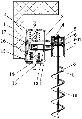
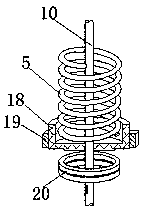
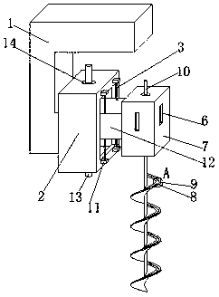
The invention belongs to the technical field of electric power construction, and particularly relates to a rotary excavating drilling machine used for electric pole installation during electric powerconstruction. By aiming at the problems that a load for a motor is huge since an existing rotary excavating driving motor frequently carries out spiral plate positive and negative rotation, the invention now puts forward the following scheme that the rotary excavating drilling machine comprise a fixed frame of a C shape, and a bearing box which is internally provided with a hollow cavity of a rectangular structure; a sliding bearing subjected to coaxial distribution is independently embedded into the middle of the top end and the middle of the bottom end of the bearing box; in addition, the middle of each of the two sliding bearings is independently in sliding connection with a spacing rod subjected to the coaxial distribution; the same sliding box is fixed between the opposite ends of thetwo spacing rods; the outer walls of two opposite sides of the sliding box are independently fixedly provided with a buffer spring; and the buffer springs are independently sheathed to the outer circumferential walls of the two spacing rods. When the rotary excavating drilling machine is used, a target position can be subjected to rotary excavation only by starting the driving motor, in addition,when soil stuck to the spiral plate needs to be removed, high-frequency vibration can be transferred to the spiral plate only by starting a vibration motor, and therefore, the soil on the spiral plate can be shaken off.

Description

technical field [0001] The invention relates to the technical field of electric power construction, in particular to a rotary drilling drill for installing electric poles for electric power construction. Background technique [0002] Rotary drilling rigs are relatively advanced large-diameter pile-forming construction equipment in China at present. They have many unique advantages and are widely used in various aspects such as construction of roads and bridges. Generally, short spiral or rotary bucket drill bits are used for pile forming operations, and the drilling and soil extraction are integrated to avoid the adverse impact on the environment caused by the use of mud wall protection to form holes. [0003] The Chinese patent document "A Measuring Device for Hole-forming Depth of Rotary Drilling Rig" with the authorized announcement number CN202000999U discloses a rotary drilling rig with a hole-forming depth measuring device. The hole-forming depth measuring device inclu...

Claims


Application Information

Patent Timeline
IPC IPC(8): E21B15/04E21B17/22E21B12/06E21B3/02E21B10/44
CPCE21B3/02E21B10/44E21B12/06E21B15/04E21B17/22
Inventor 何学峰
Owner 何学峰
Learn More