Reflective road marking line synthesis marking device
A marking device and road marking technology, which is applied in the field of reflective road marking synthesis marking device, can solve the problems of cumbersome work and low work efficiency, and achieve the effects of controlling speed and steering, improving quality and increasing friction
- Summary
- Abstract
- Description
- Claims
- Application Information
AI Technical Summary
Problems solved by technology
Method used
Image
Examples
Embodiment 1
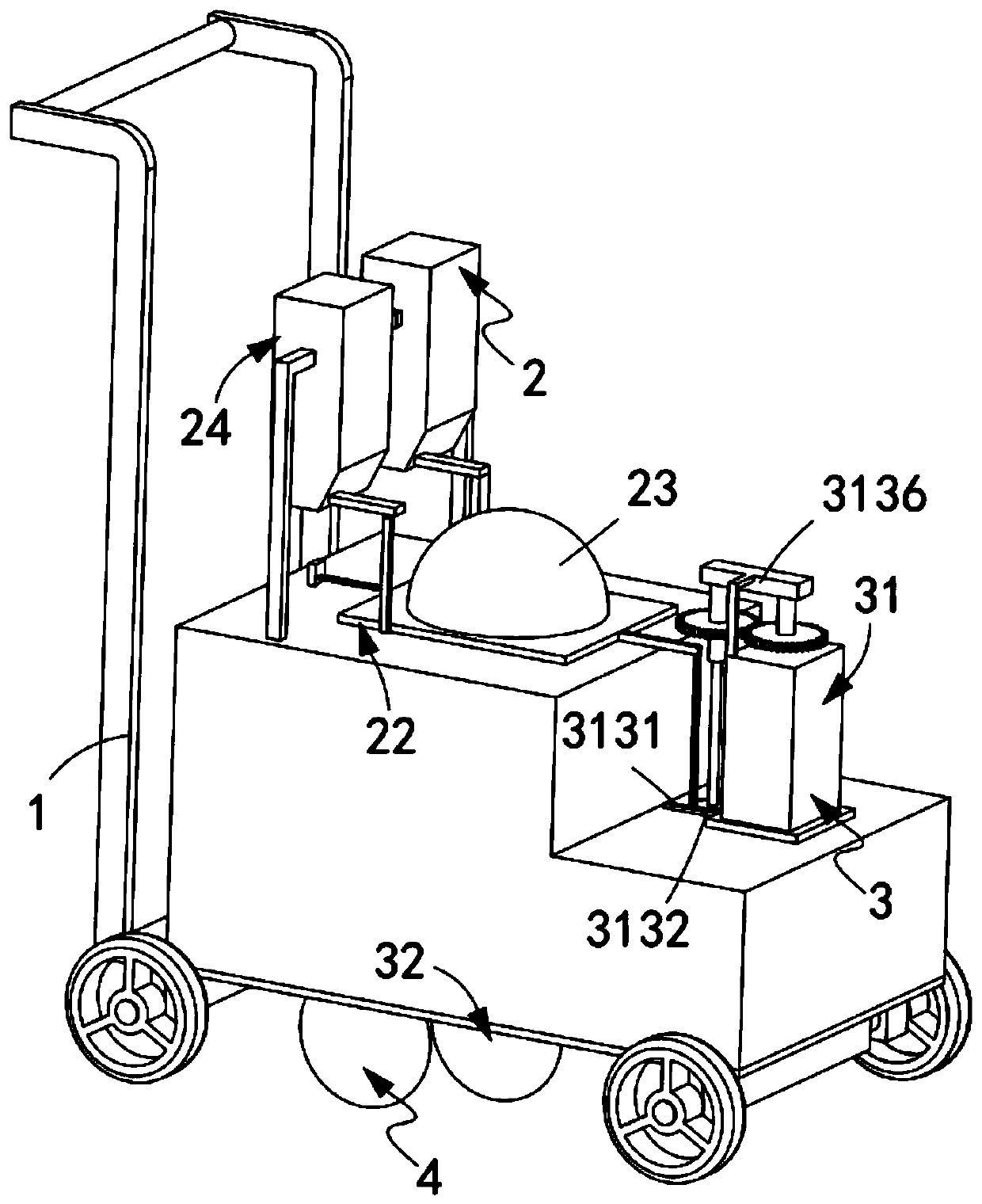
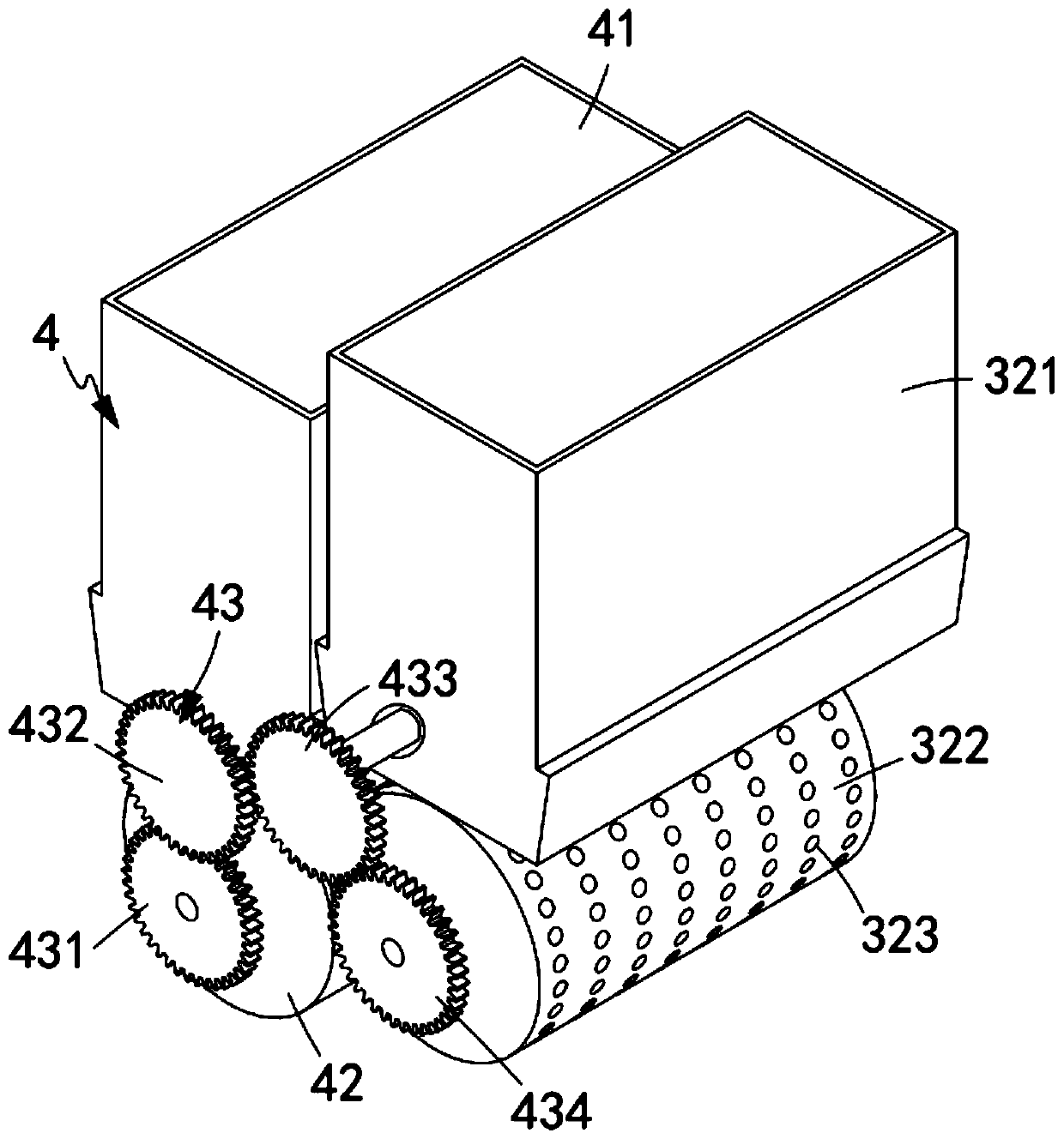
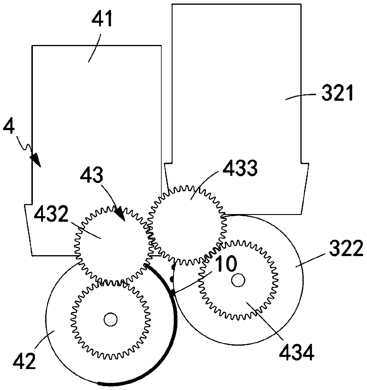
[0078] Such as figure 1 , Figure 6 and Figure 7 As shown, a reflective road marking synthetic marking device includes a marking car 1, and also includes a marking paint production device 2 installed on the marking car 1, a glass bead discharge device 3 and a paint marking device 4;
[0079] The marking paint production device 2 comprises a reaction tank 21, a discharge assembly 22 arranged on the reaction tank 21, a transfer box 23 arranged above the discharge assembly 22, positioned above the transfer box 23 and connected to The transfer box 23 is communicated with a supply assembly 24 and a mixing assembly 25 located in the reaction tank 21 and directly below the discharge assembly 22;
[0080] The glass bead discharge device 3 includes a blanking assembly 31 and a pressing assembly 32 located below the blanking assembly 31, and the pressing assembly 32 performs a uniform pressing work on the glass beads 10;
[0081] The paint scribing device 4 is located on one side o...
Embodiment 2
[0124] Such as Figure 17-Figure 24 As shown, the components that are the same as or corresponding to those in the first embodiment are marked with the corresponding reference numerals in the first embodiment. For the sake of simplicity, only the differences from the first embodiment will be described below. The difference between this embodiment two and embodiment one is:
[0125] further, such as Figure 17 , Figure 23 As shown, the mixing assembly 25 includes:
[0126] Temporary storage box 251, the upper surface of the temporary storage box 251 is attached to the lower surface of the discharge assembly 22. The temporary storage box 251 is a cavity structure and an inclined plate 252 is arranged therein. The inclined plate 252 is set for an inverted figure-of-eight structure; and
[0127] A mixing part 253, the mixing part 253 is arranged directly below the output end of the temporary storage box 251, and the mixing part 253 is installed on the reaction tank 21, which ...
PUM
 Abstract
Description
Claims
Application Information
 - R&D
- Intellectual Property
- Life Sciences
- Materials
- Tech Scout
- Unparalleled Data Quality
- Higher Quality Content
- 60% Fewer Hallucinations
Browse by: Latest US Patents, China's latest patents, Technical Efficacy Thesaurus, Application Domain, Technology Topic, Popular Technical Reports.
© 2025 PatSnap. All rights reserved.Legal|Privacy policy|Modern Slavery Act Transparency Statement|Sitemap|About US| Contact US: help@patsnap.com


