
Clamp for machining flange plate

A fixture and center plate technology, applied in the field of flange processing fixtures, can solve the problems of poor connection performance, difficult positioning of ends, poor control performance, etc., and achieve the effect of convenient fitting and positioning and improving firmness.

Pending Publication Date: 2020-07-10
苏州利航精密制造有限公司
View PDF0 Cites 2 Cited by
  • Summary
  • Abstract
  • Description
  • Claims
  • Application Information

AI Technical Summary

Problems solved by technology

[0004] The purpose of the present invention is to provide a fixture for flange processing to solve the problem that the existing fixture proposed in the background art is not well-proportioned in end design, that is, the structural design between parts is very messy, making it extremely difficult to use , it is difficult to cooperate well with each component, and the connection performance is poor. At the same time, there is no good assembly structure installed on the bottom of the device body, which makes it difficult to position the end in accordance with the actual use environment. There is such a controllability poor problem

Method used


Image

  • Clamp for machining flange plate
  • Clamp for machining flange plate
  • Clamp for machining flange plate

Examples


Embodiment Construction

[0027] The following will clearly and completely describe the technical solutions in the embodiments of the present invention with reference to the accompanying drawings in the embodiments of the present invention. Obviously, the described embodiments are only some, not all, embodiments of the present invention.

[0028] In the description of the present invention, unless otherwise stated, the meaning of "plurality" is two or more; the terms "upper", "lower", "left", "right", "inner", "outer" , "front end", "rear end", "head", "tail", etc. indicate the orientation or positional relationship based on the orientation or positional relationship shown in the drawings, and are only for the convenience of describing the present invention and simplifying the description, rather than Nothing indicating or implying that a referenced device or element must have a particular orientation, be constructed, and operate in a particular orientation should therefore not be construed as limiting ...

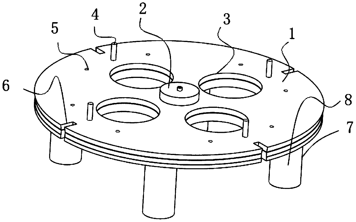

PUM


Abstract

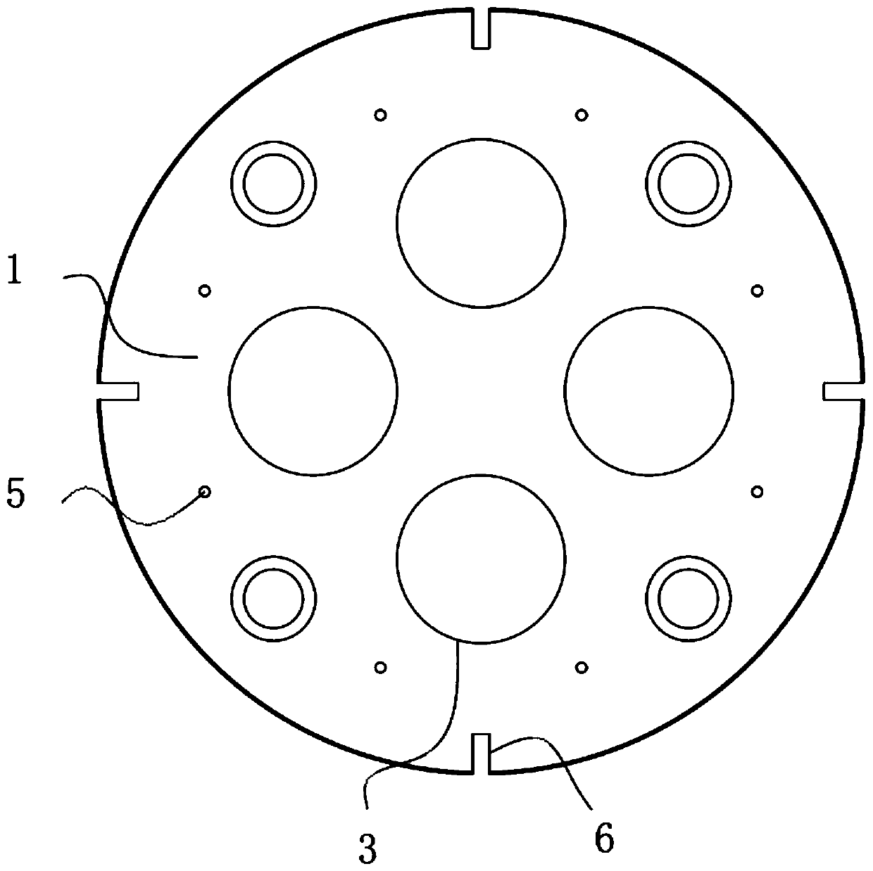
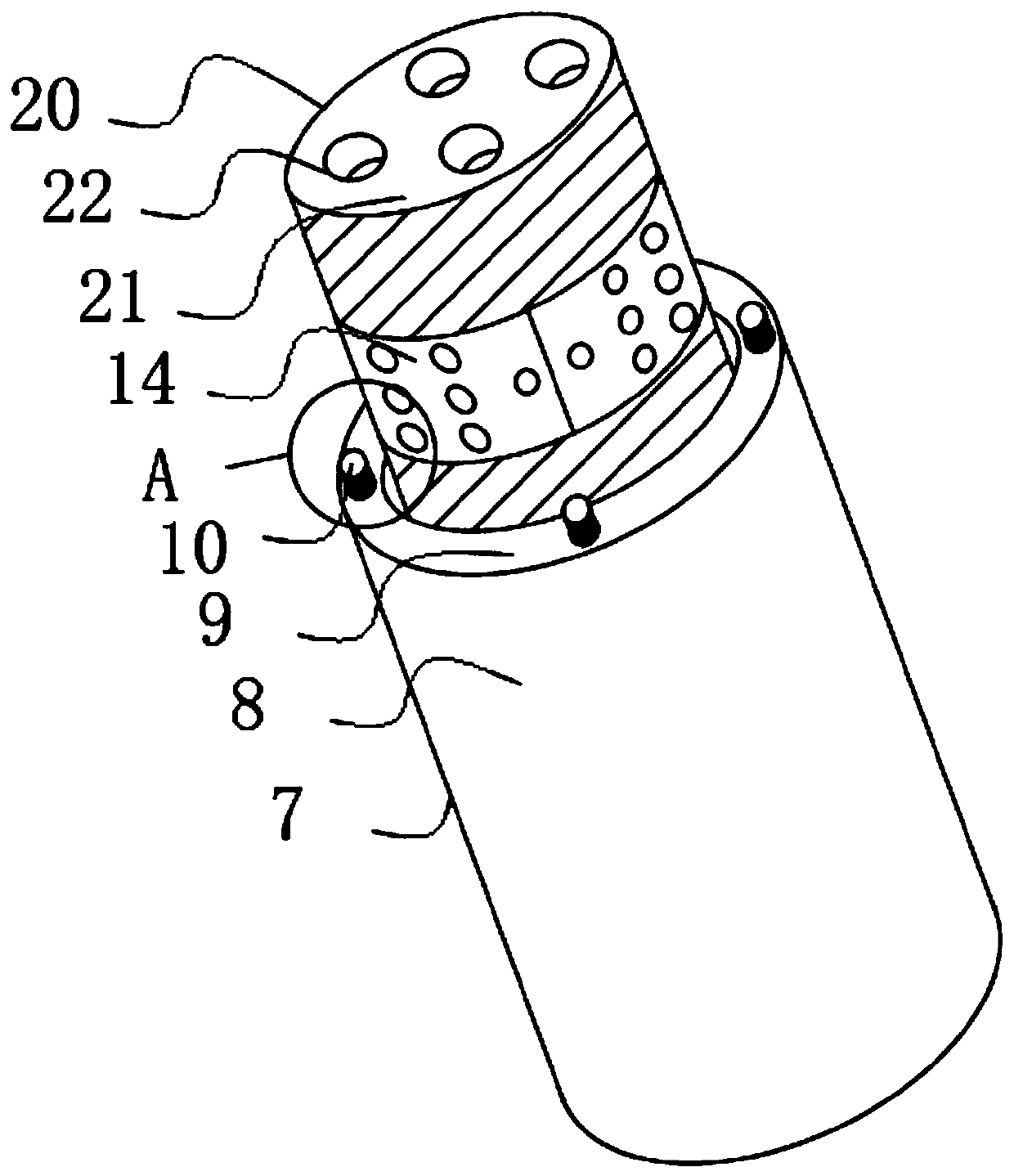
The invention relates to a clamp for machining a flange plate. The clamp comprises a middle disc and end fixing mechanisms, wherein a center top is arranged at the top end of the middle of the middledisc, ports are formed in the side end of the middle disc in a penetrating mode, embedding columns are fixed to the top of the side end of the middle disc, embedding holes are formed in the end wall of the side, close to the embedding columns, of the middle disc in a penetrating mode, embedding channels are formed in the side wall of the middle disc, the end fixing mechanisms are arranged at the bottom end of the middle disc, the inner sides of the top ends of the end fixing mechanisms are provided with inner fixing mechanisms, and the top ends of the end fixing mechanisms are provided with upper fixing mechanisms. The clamp for machining the flange plate has the beneficial effects that by means of the inwards-sunken design of buckle openings, buckling can be conveniently conducted throughfingers, at the moment, the buckle openings can be rotated by a hand to enable an upper table to rotate synchronously, and meanwhile the upper table, and the end fixing mechanisms and the inner fixing mechanisms at the end of the upper table can be rotationally adjusted out to be used in an exposed mode, the bottom of a device body can be fully utilized conveniently, the butt joint effect of thebottom of the device body is improved, and assembling is convenient.

Description

technical field [0001] The invention relates to the technical field of flange processing, in particular to a fixture for flange processing. Background technique [0002] Flanges are referred to as flanges for short, and they are just a general term. They usually refer to opening several holes for fixing on the periphery of a disc-like metal body for connecting other things. This thing is widely used in machinery, so it looks strange, as long as it is called a flange, it generally uses a fixture during processing to facilitate the positioning of the flange. [0003] Due to the uneven design of the end of the existing fixture, that is, the messy structural design between the parts, it is extremely difficult to use, and it is difficult to cooperate well with each other, and the connection performance is poor. At the same time, the bottom of the device body There is no better assembly structure installed, which makes it difficult to position the ends in accordance with the actu...

Claims


Application Information

Patent Timeline
Patent Type & Authority Applications(China)
IPC IPC(8): B25B11/00
CPCB25B11/00
Inventor 李桂军
Owner 苏州利航精密制造有限公司
Learn More