
Multi-section forming reamer for processing automobile valve sleeve

A valve sleeve and reamer technology, applied in reamers, metal processing equipment, manufacturing tools, etc., can solve the problems of iron filings scratching the hole wall, edge wear, tool life reduction, etc., to facilitate chip removal and cooling of the blade mouth, to ensure concentricity requirements, and to improve the effect of cooling effect

Inactive Publication Date: 2020-07-10
SUZHOU AHNO PRECISION CUTTING TECH CO LTD
View PDF0 Cites 1 Cited by
  • Summary
  • Abstract
  • Description
  • Claims
  • Application Information

AI Technical Summary

Problems solved by technology

[0004] 2. High roughness requirements in the hole;
[0007] 1. It is difficult to remove chips in multi-stage stepped holes, and there is a risk of iron chips scratching the hole wall;
[0008] 2. The coaxiality requirements of several sections of precision holes are strict, and they must be processed together, which increases the difficulty of production;
[0009] 3. If the tool groove is too long, it will easily lead to poor tool rigidity and larger runout, resulting in reduced tool life and poor workpiece accuracy;
[0010] 4. The cooling effect of the tool is not obvious, resulting in accelerated wear of the cutting edge

Method used


Image

  • Multi-section forming reamer for processing automobile valve sleeve
  • Multi-section forming reamer for processing automobile valve sleeve
  • Multi-section forming reamer for processing automobile valve sleeve

Examples


Embodiment Construction

[0034] The embodiments of the present invention will be described in detail below in conjunction with the accompanying drawings, so that the advantages and features of the present invention can be more easily understood by those skilled in the art, so as to define the protection scope of the present invention more clearly.

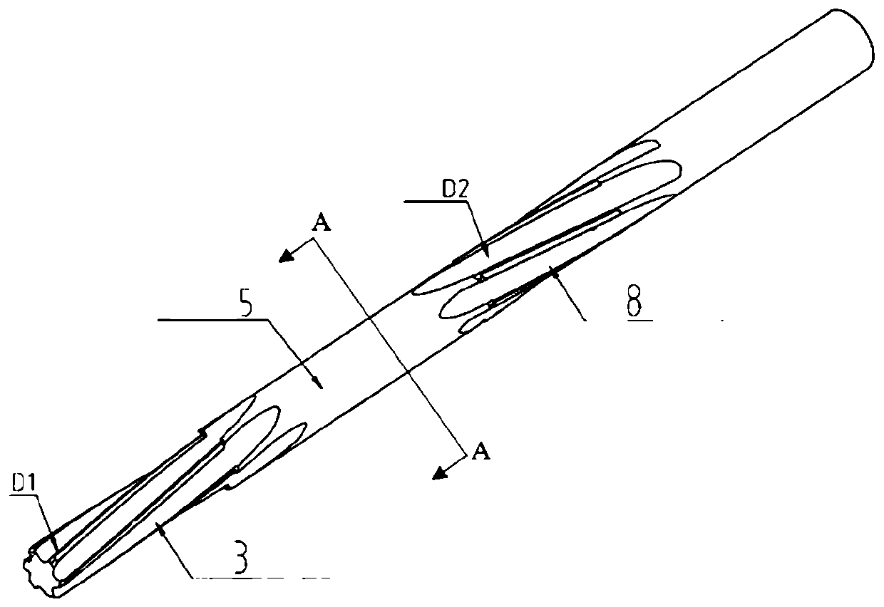
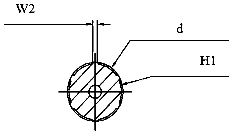
[0035] Such as Figure 1-11 As shown, a multi-section forming reamer for processing automobile valve sleeves includes a cutter body 1 and a handle 9. The cutter body 1 and the handle 9 are coaxial cylinders centered on a common axis 4, and the cutter body 1 has four sections. , are respectively: cylinder diameter D1, guide column 5, cylinder diameter D2 and tool holder 9 (cylindrical diameter D3), and there are two sections of chip removal grooves on the cutter body 1: left-handed knife groove 3 and right-handed knife groove 8, There is a forming chamfer at the front section of the head, and there are left peripheral cutting edge 2 and right peripheral cut...


PUM


Abstract

The invention discloses a multi-section forming reamer for processing an automobile valve sleeve. A left peripheral blade and a right peripheral blade are sequentially arranged on a knife body; a guide column is arranged between the left peripheral blade and the right peripheral blade; a left knife rotating slot with left helixes is formed in the left peripheral blade; a right knife rotating slotwith right helixes is formed in the right peripheral blade; an internal cold hole which is formed along a center axis is formed inside the knife body; one end, towards the head part of the knife body,of the internal cold hole is sealed; and the head of the knife body is provided with a forming chamfer angle. The multi-section forming reamer for processing the automobile valve sleeve provided by the invention, a left-helix design is adopted for discharging chips downwards, and a right-helix design is adopted for upwards discharging chips, so that a phenomenon that scrap iron cannot be discharged as a chip discharge slot is too long is avoided; a guide column is additionally arranged to raise a supporting column, so that hole precision is improved; a forming chamfer design is adopted, chamfering for connecting a R angle to a transition angle is made after conventional chamfering, so that roughness of hole walls can be improved in a cutting process; and the left knife rotating slot adopts front punching and side cooling, and a right knife rotating slot adopts back punching and side cooling, so that a chip discharge direction is met, chip removal and cutting edge cooling are facilitated better, and therefore, cooling effect is improved.

Description

technical field [0001] The invention belongs to the technical field of milling cutters, in particular to a multi-section forming reamer for processing automobile valve sleeves. Background technique [0002] The automobile valve sleeve needs to be used together with the valve core, and the degree of cooperation directly affects the service life of the automobile valve sleeve and valve core, which makes it have the following characteristics: [0003] 1. There are multiple forming steps; [0004] 2. High roughness requirements in the hole; [0005] 3. Strict concentricity requirements (most important). [0006] The difficulty of conventional valve sleeve precision hole processing technology lies in: [0007] 1. It is difficult to remove chips in multi-stage stepped holes, and there is a risk of iron chips scratching the hole wall; [0008] 2. The coaxiality requirements of several sections of precision holes are strict, and they must be processed together, which increases t...

Claims


Application Information

Patent Timeline
Patent Type & Authority Applications(China)
IPC IPC(8): B23D77/00B23D77/14
CPCB23D77/006B23D77/14B23D2277/30
Inventor 余洪马提于道海
Owner SUZHOU AHNO PRECISION CUTTING TECH CO LTD
Learn More