
Mobile wall wiring structure

A wiring structure and mobile technology, applied in the direction of electrical components, etc., can solve the problems that the wall is not easy to handle, the installation depth of the junction box is inconsistent, and the beauty of the wall is affected.

Inactive Publication Date: 2020-07-07
新沂市瑞阳新型墙体建材有限公司
View PDF0 Cites 1 Cited by
  • Summary
  • Abstract
  • Description
  • Claims
  • Application Information

AI Technical Summary

Problems solved by technology

The junction bottom box in the shear wall is pre-buried before the wall is closed, and the junction bottom box is pre-placed on the shear wall reinforcement. However, after the formwork is removed, some shear walls need to be plastered on the wall to compensate for the shear wall. The structural deviation of the force wall makes it difficult to handle the wall at the edge of the junction box, resulting in inconsistent installation depths of the junction box on the wall, which affects the appearance of the wall

Method used


Image

  • Mobile wall wiring structure

Examples


Embodiment 1

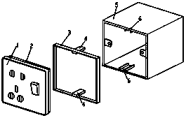
[0011] Embodiment 1: A mobile wall wiring structure, including a wall inner box 5 and an outer box frame 3; The inner side and the inner side below the wall inner box 5 are respectively provided with guide rails 6; 3. Inserting strips 4 adapted to guide rails 6 are respectively provided on the inner side of the bottom. The construction process of the adjustable wall junction bottom box is as follows: First, the wall inner box 5 is reinforced on the shear wall or column steel bars, and then the mold is closed to ensure that the edge of the wall inner box 5 is firmly attached to the formwork. After the concrete is poured and the formwork is removed, the residue around the inner box 5 of the wall is cleaned. If the concrete structure meets the requirements, then proceed directly to the later decoration construction, and then use the common wire box panel in the market for installation. If there is deviation in the concrete structure, when the wall or column surface needs to be ...

Embodiment 2

[0012] Embodiment 2: A mobile wall wiring structure, including a wall inner box 5 and an outer box frame 3; The inner side and the inner side below the wall inner box 5 are respectively provided with guide rails 6; 3. Inserting strips 4 adapted to guide rails 6 are respectively provided on the inner side of the bottom. The guide rails 6 are respectively arranged on the inner middle part above the wall inner box 5 and the inner middle part below the wall inner box 5; Medial middle. The construction process of this embodiment is the same as that of Embodiment 1.


PUM


Abstract

The invention relates to a mobile wall wiring structure which comprises a wall inner box and an external box frame. The wall inner box is provided with an upper face, a lower face, a left face and a right face, and guide rails are arranged on the inner side of the upper face of the wall inner box and the inner side of the lower face of the wall inner box respectively. The external connection box frame is provided with four faces the same as those of the wall inner box, and inserting strips matched with the guide rails are arranged on the inner side of the upper face of the external connectionbox frame and the inner side of the lower face of the external connection box frame respectively. The wiring bottom box has the advantages that the plastering thickness of the outer side of the edge of the wiring bottom box is increased, during plastering, the wall surface around the wiring box can be better processed, and during later installation of the panel of the wiring bottom box, the integrating degree of the panel and the wall surface is extremely good and seamless, so that the wall surface is attractive. According to the invention, rework or later decoration repair work caused by poorappearance quality around the wiring bottom box is saved, and a lot of manpower and materials are saved.

Description

technical field [0001] The technical field of wall electrical accessories of the present invention is specifically a movable wall wiring structure. Background technique [0002] With the continuous development of high-rise building technology, the shear wall structure has become the mainstream structural form of buildings. The junction bottom box in the shear wall is pre-buried before the wall is closed, and the junction bottom box is pre-placed on the shear wall reinforcement. However, after the formwork is removed, some shear walls need to be plastered on the wall to compensate for the shear wall. The structural deviation of the force wall makes it difficult to handle the wall at the edge of the junction box, resulting in inconsistent installation depths of the junction box on the wall, which affects the appearance of the wall. Contents of the invention [0003] The technical problem to be solved by the present invention is to provide a movable wall connection structure...

Claims


Application Information

Patent Timeline
Patent Type & Authority Applications(China)
IPC IPC(8): H02G3/12
CPCH02G3/121
Inventor 乔雷
Owner 新沂市瑞阳新型墙体建材有限公司
Learn More