A motor torque ripple test bench and test method

A technology for test testing and motor torque, used in motor generator testing, torque measurement, measuring devices, etc., can solve the problems of narrow test range, few factors to consider, large errors, etc., to meet the measurement and expansion of high-frequency area. Measurement range, the effect of expanding the test range

Active Publication Date: 2021-02-02
SHENZHEN XILIN ELECTRICAL TECH
View PDF12 Cites 0 Cited by
  • Summary
  • Abstract
  • Description
  • Claims
  • Application Information

AI Technical Summary

Problems solved by technology

This method is simple to operate, but there are too few considerations, and it is easily affected by load fluctuations and mechanical structure resonance during the measurement process, resulting in large errors.
And subject to the torsion bar stiffness cannot be changed in a large range, it can only be used at low speeds, and the test range is narrow
Although the balance method overcomes the torque fluctuation in the transmission process compared with the direct method, it still uses a load, which cannot avoid load fluctuations, and the motor under test needs to protrude from both ends, so it is not suitable for testing ordinary motors
The stator-rotor separation method, although it has made breakthroughs and innovations in avoiding non-measurement torque fluctuations, it is still not widely used in the measurement of motor torque fluctuations.

Method used


Image

  • A motor torque ripple test bench and test method
  • A motor torque ripple test bench and test method
  • A motor torque ripple test bench and test method

Examples


Embodiment Construction

[0033] The present invention will be described in detail below in conjunction with the accompanying drawings and specific embodiments. This example takes a 3.6kW permanent magnet synchronous motor as an example to illustrate the establishment and testing process of the torque ripple test system.

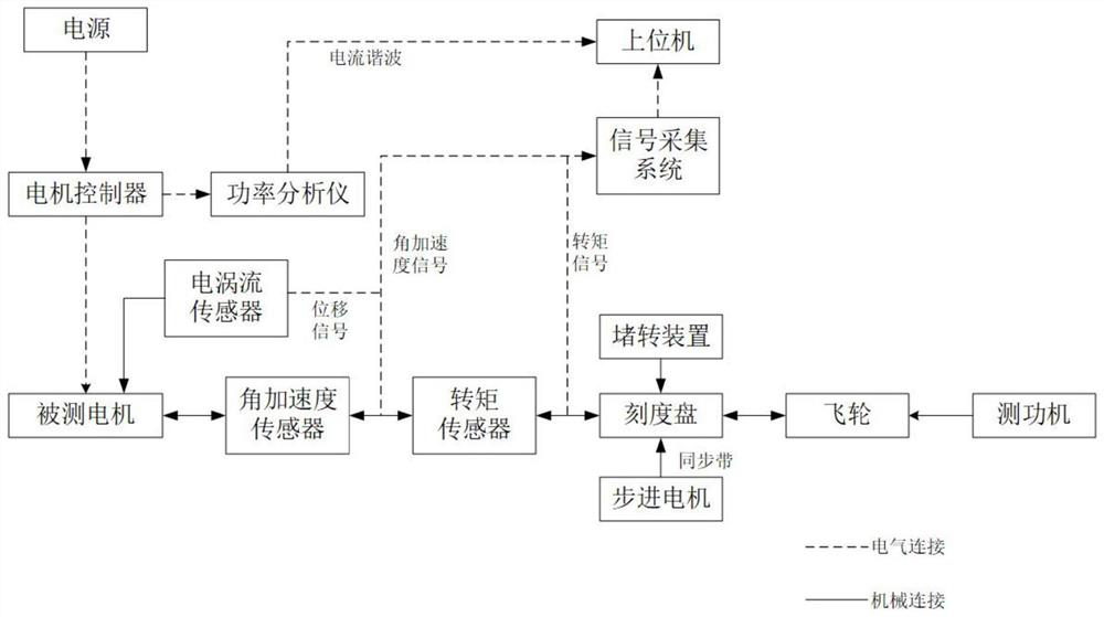
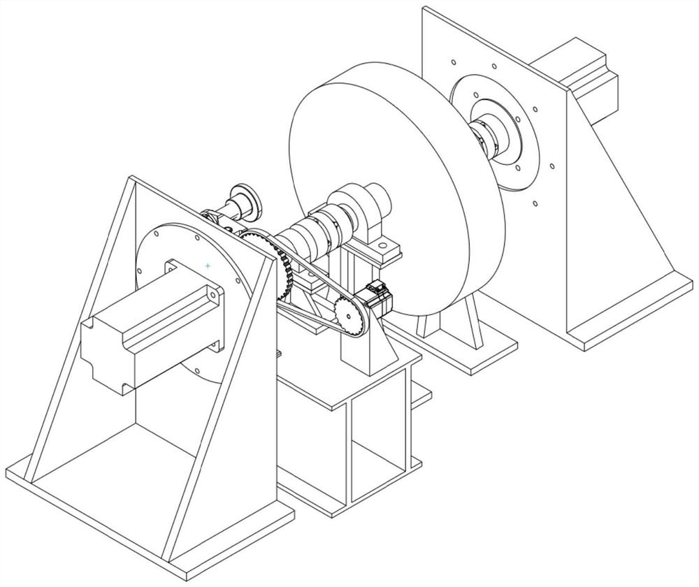
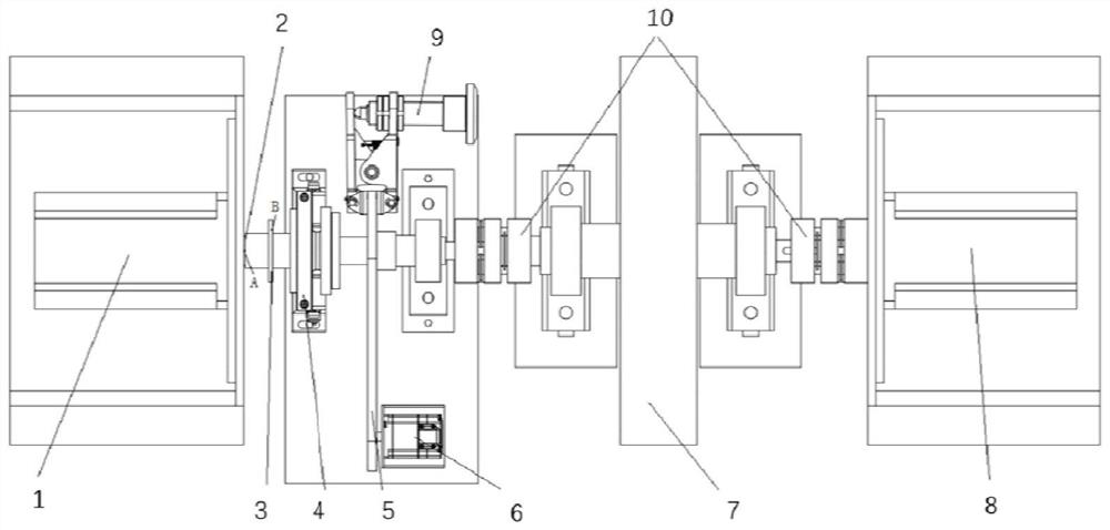
[0034] combine Figure 1-3 As shown, a kind of motor torque ripple test bench of the present invention comprises: motor controller, power supply, power analyzer, host computer, signal acquisition system, tested motor 1, eddy current displacement sensor 2, angular acceleration sensor 3. Torque sensor 4, synchronous belt transmission structure 5, stepping motor 6, elastic coupling, flywheel 7, dynamometer 8, brake 9 and elastic coupling 10.

[0035] The motor 1 under test includes a rotor shaft A;

[0036] The synchronous belt transmission structure includes a large pulley, a small pulley and a synchronous belt, and the synchronous belt transmission connects the large pulley and the ...


PUM

PropertyMeasurementUnit
distanceaaaaaaaaaa

Abstract

The application relates to a motor torque pulsation test bench and test method, which is provided with a synchronous belt transmission structure, and precisely controls the precision of the rotor rotation position through a large pulley. Through multi-position stalling, the torque fluctuation during the rotor movement can be obtained; by using the torque sensor in the low frequency area, and using the angular acceleration sensor in the high frequency area, the measurement range of the cogging torque is expanded; it is suitable for the whole motor Cogging torque measurements in the frequency domain. The test bench combines stall and inertial loading. On a test bench, the torque fluctuation of the motor within one rotation period can be characterized by the stall method, and the cogging torque fluctuation of the motor can also be directly tested. The influence of the torque fluctuation of the dynamometer itself can be reduced as much as possible through the large inertia flywheel. In addition, an elastic coupling is used to eliminate the influence of coaxiality, eccentricity and vibration in the transmission chain on the sensor side, and prevent the sensor from being damaged due to vibration.

Description

technical field [0001] The present application relates to the field of motor testing, in particular to a torque ripple test bench and a test method combining locked rotor and inertial loading. Background technique [0002] In the electric drive system, torque ripple is an important source of motor vibration and noise, and is one of the key issues to improve the quality of the electric drive system. Torque ripple can also cause torque vibration, which may cause the motor to resonate, increase various losses, shorten the life of the motor, and reduce the reliability and stability of work. Therefore, it is very important to accurately test the motor torque ripple with the design of the electric drive system and the optimization of the motor body and control system. The main reasons for the torque ripple of the motor are the cogging torque of the motor itself and the unbalanced magnetic pull on the rotor shaft due to machining errors. [0003] Some existing torque measurement ...

Claims


Application Information

Patent Timeline
Patent Type & Authority Patents(China)
IPC IPC(8): G01L3/22G01R31/34
CPCG01L3/22G01R31/34
Inventor 张承宁赵越杨永喜杨国辉滕继晖张硕
Owner SHENZHEN XILIN ELECTRICAL TECH
Why Eureka
Try Eureka