Washing machine
A washing machine and washing tub technology, applied in the field of washing machines, can solve the problems of long water intake time, difficult temperature control, and inability to achieve capacity expansion.
- Summary
- Abstract
- Description
- Claims
- Application Information
AI Technical Summary
Problems solved by technology
Method used
Image
Examples
Embodiment 1
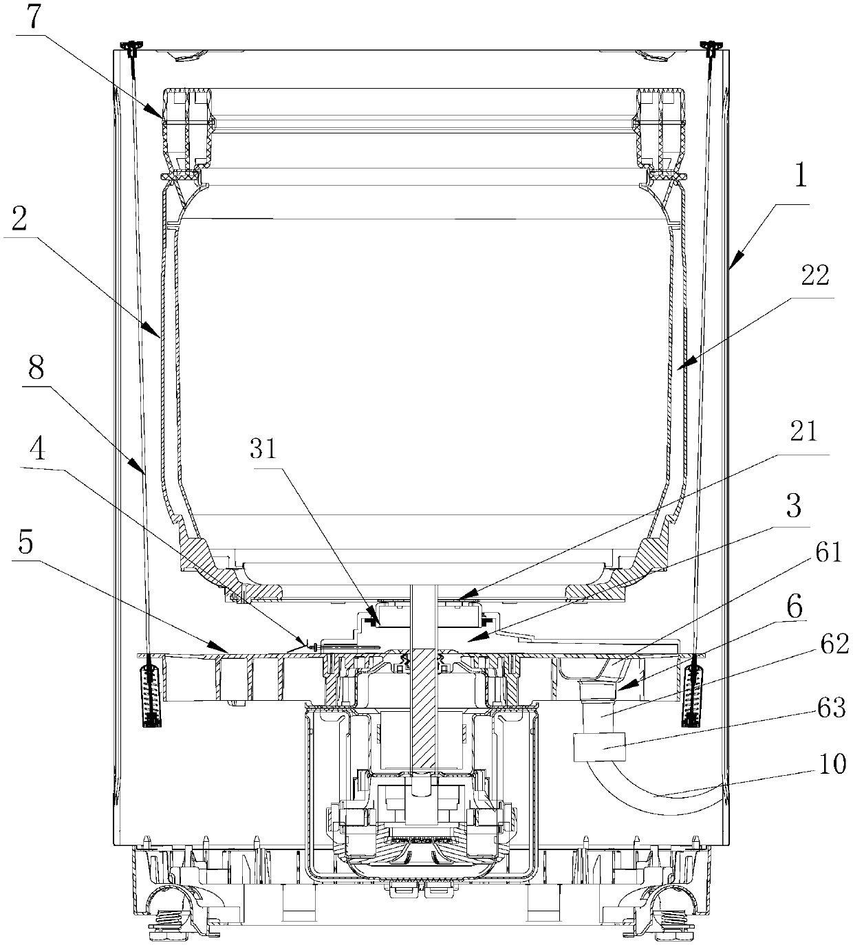
[0057] Such as figure 1 As shown, the heating chamber 3 described in this embodiment includes a first drainage channel 31, and the heating unit 4 is arranged in the first drainage channel 31;
[0058] Preferably, the heating unit 4 is disposed directly below the first drain port 21 and / or deviates from the water inlet of the drain component 6 , that is, directly above the second drain port 61 . The setting structure of the heating unit deviated directly below the first water outlet can prevent damage to the heating unit caused by the impact of the water flow on the heating unit or water leakage at the installation caused by the shaking of the heating unit during drainage. The upper setting structure can prevent the lint from accumulating and winding on the heating unit during drainage, which will affect the heating efficiency and drainage speed.
Embodiment 2
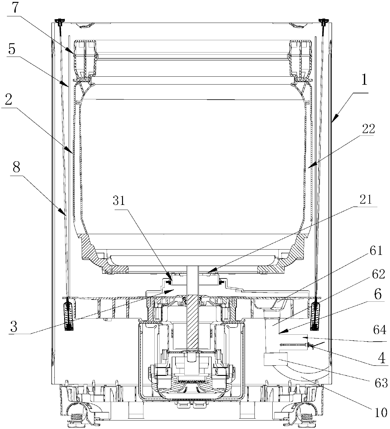
[0060] Such as figure 2 As shown, the heating chamber 3 described in this embodiment further includes a drainage component 6, and the heating unit 4 is arranged in the second drainage channel 62;
[0061] Preferably, the side wall of the second drainage channel 62 is provided with a side channel 64 , and the heating unit 4 is arranged in the side channel 64 . This structure can reduce the impact of the drainage water flow on the heating unit, and at the same time prevent the heating unit from affecting the drainage speed.
[0062] The washing machine of the present invention can adopt the arrangement of the heating unit in Embodiment 1 or Embodiment 2 alone, or a combination of the two, so as to improve the heating efficiency.
Embodiment 3
[0064] Such as Figure 5 As shown, the first drainage channel 31 in this embodiment includes a first cavity 311 and a second cavity 312 , and the first cavity 311 and the second cavity 312 are connected in a sealed manner so that they can rotate relative to each other. The peripheral wall of the first cavity 311 at least partially extends to the inside of the second cavity 312, and a sealing ring 313 is sleeved on the peripheral wall of the first cavity 311, and one side of the sealing ring 313 is in contact with the first cavity. The body 311 is in sealing contact, and the other side is in sealing contact with the second cavity 312 .
[0065] Further, the sealing ring 313 is a skeleton oil seal, and is fixedly installed on the inner wall of the second cavity 312 close to the end of the first cavity 311 , the inner ring of the sealing ring 313 is in sliding contact with the outer peripheral wall of the first cavity 311 .
[0066] Preferably, the upper end of the first cavity ...
PUM
 Abstract
Description
Claims
Application Information
 - R&D Engineer
- R&D Manager
- IP Professional
- Industry Leading Data Capabilities
- Powerful AI technology
- Patent DNA Extraction
Browse by: Latest US Patents, China's latest patents, Technical Efficacy Thesaurus, Application Domain, Technology Topic, Popular Technical Reports.
© 2024 PatSnap. All rights reserved.Legal|Privacy policy|Modern Slavery Act Transparency Statement|Sitemap|About US| Contact US: help@patsnap.com


