Purified water direct drinking machine
A direct drinking machine and pure water technology, applied in beverage preparation devices, household appliances, applications, etc., can solve the problems of increased heating frequency of drinking fountains, imperfect insulation system, increased energy consumption, etc., and achieve the effect of avoiding heating
- Summary
- Abstract
- Description
- Claims
- Application Information
AI Technical Summary
Problems solved by technology
Method used
Image
Examples
Embodiment 1
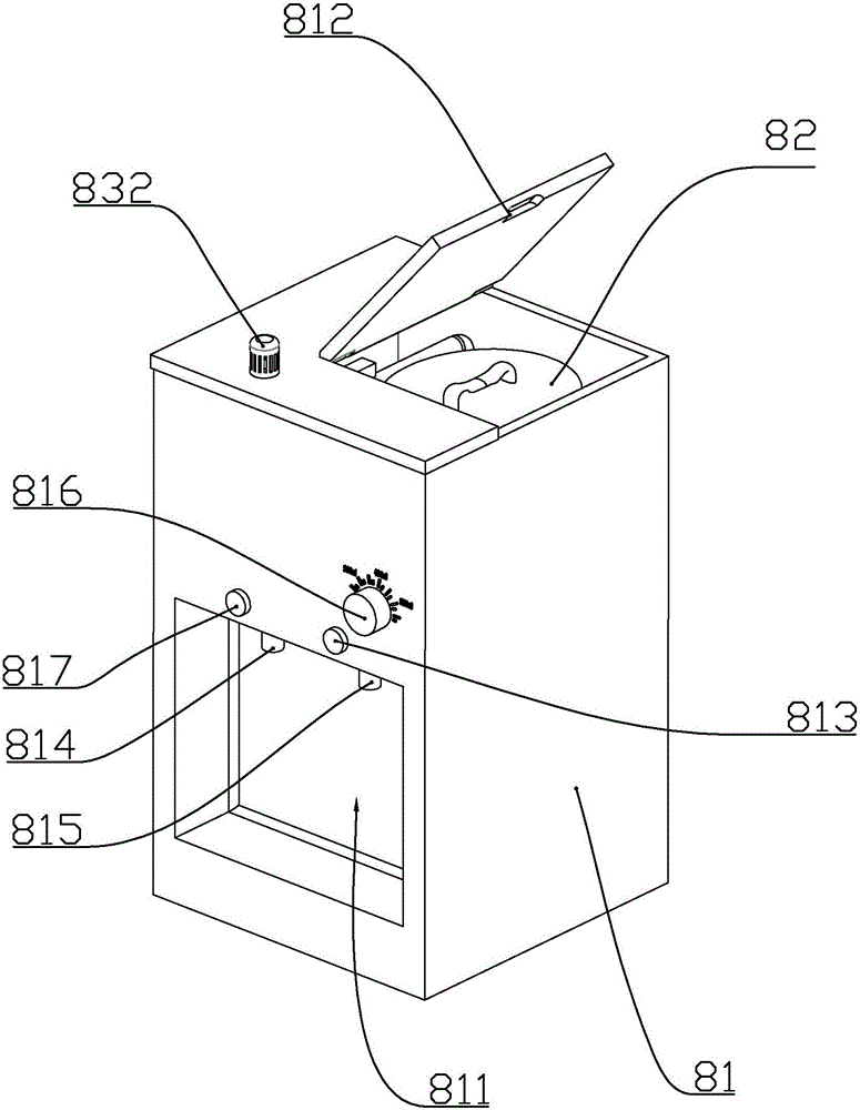
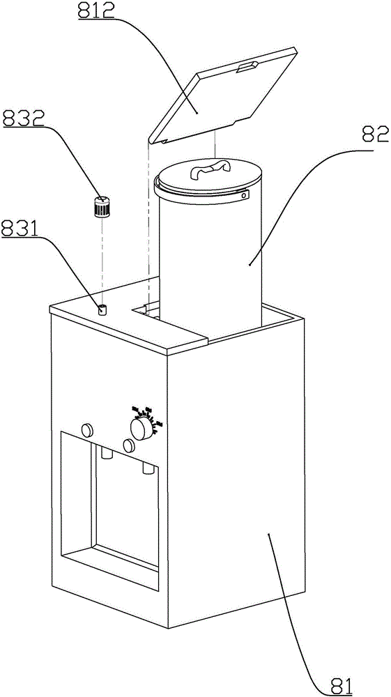
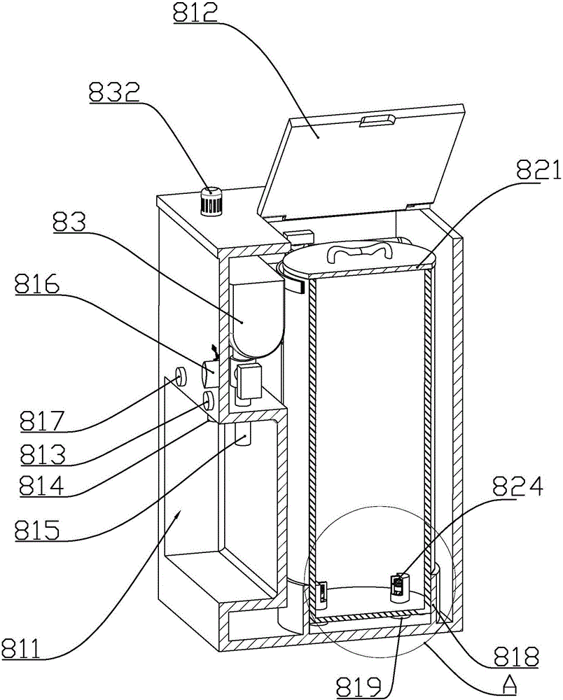
[0059] according to Figure 1 to Figure 20 As shown, a pure water direct drinking machine described in this embodiment includes a cabinet 81 and a water tank 82 installed inside the cabinet 81 , a heating tank 83 , a filter P, a water pump 9 and a general control circuit board 85 .
[0060] A water receiving chamber 811 is formed under the front part of the cabinet 81 , and a cold water outlet pipe 814 and a boiling water outlet pipe 815 are installed on the upper part of the water receiving chamber 811 .
[0061] The front part of the cabinet 81 is located above the water receiving cavity and is provided with a water volume adjusting knob 816, a cold water receiving switch 817 and a boiling water receiving switch 813.
[0062] A flip cover 812 is rotatably connected to the top of the cabinet 81 above the water tank 82 .
[0063] The inner bottom of the cabinet 81 is formed with a water tank base 818, and the bottom of the water tank base 818 is installed with two vertical wa...
Embodiment 2
[0091] In this embodiment, on the basis of Embodiment 1, an electronic scale module for measuring the weight of the water tank is installed on the base of the water tank. The electronic scale module is connected to the general control circuit board, and the general control circuit board is also connected to a buzzer.
[0092] When the weight of the water tank measured by the electronic scale module is less than the set value, the main control circuit board controls the buzzer to alarm, prompting the user to replace the tap water in the water tank.
[0093] The weight of the water tank is about 200g, and the set value can be set as 0.5-1kg. In this way, when the water in the water tank is about to run out, the concentration of dirt and impurities in the water is already high, and the buzzer reminds the user to change the water in time , Avoid tap water with too many impurities to pollute the filter and various water pipes.
Embodiment 3
[0095] In this embodiment, on the basis of Embodiment 1 or 2, in order to ensure the high efficiency of the filter and its self-cleaning ability, the water pump is further improved. according to Figure 21 to Figure 32 As shown, the water pump includes a guide housing 91 with an upper end closed and an open lower end, a circular tubular pump housing 92 fixedly connected to the lower end of the guide housing, a pump cover 93 fixedly connected to the lower end of the pump housing, and slidably mounted on the pump housing The inner piston 94, and three electromagnets installed in the guide housing to drive the piston to move up and down.
[0096] The three electromagnets include a third electromagnet 963 that is fixedly mounted on the top of the guide housing, and a second electromagnet 962 and a first electromagnet 961 that are slidably installed in the guide housing. below the iron.
[0097] The electromagnet includes an annular iron core 9601, a coil winding 9603 fixedly con...
PUM
 Abstract
Description
Claims
Application Information
 - R&D
- Intellectual Property
- Life Sciences
- Materials
- Tech Scout
- Unparalleled Data Quality
- Higher Quality Content
- 60% Fewer Hallucinations
Browse by: Latest US Patents, China's latest patents, Technical Efficacy Thesaurus, Application Domain, Technology Topic, Popular Technical Reports.
© 2025 PatSnap. All rights reserved.Legal|Privacy policy|Modern Slavery Act Transparency Statement|Sitemap|About US| Contact US: help@patsnap.com


