
Numerical control machine tool rotary cutter disc with cutter heads being replaced conveniently

A technology of CNC machine tools and rotary cutterheads, which is applied in milling cutters, milling machine equipment, manufacturing tools, etc., and can solve problems such as difficult removal or installation, and troublesome operation.

Active Publication Date: 2020-07-07
TAIZHOU BETTER TOOLS CO LTD
View PDF8 Cites 0 Cited by
  • Summary
  • Abstract
  • Description
  • Claims
  • Application Information

AI Technical Summary

Problems solved by technology

[0005] The object of the present invention is to provide a kind of CNC machine tool rotary cutter head that is easy to replace the cutter head, to solve the need to replace the alloy cutter head after the existing peripheral milling cutter cutter head with the above structure has been used for a period of time, because these cutter heads mostly use screws It is fixedly installed on each tool seat of the cutter head, so when the cutter head needs to be replaced after a period of use, the operation is troublesome, and it is not easy to remove or install it at one time

Method used


Image

  • Numerical control machine tool rotary cutter disc with cutter heads being replaced conveniently
  • Numerical control machine tool rotary cutter disc with cutter heads being replaced conveniently
  • Numerical control machine tool rotary cutter disc with cutter heads being replaced conveniently

Examples


Embodiment Construction

[0027] The following will clearly and completely describe the technical solutions in the embodiments of the present invention with reference to the accompanying drawings in the embodiments of the present invention. Obviously, the described embodiments are only some, not all, embodiments of the present invention.

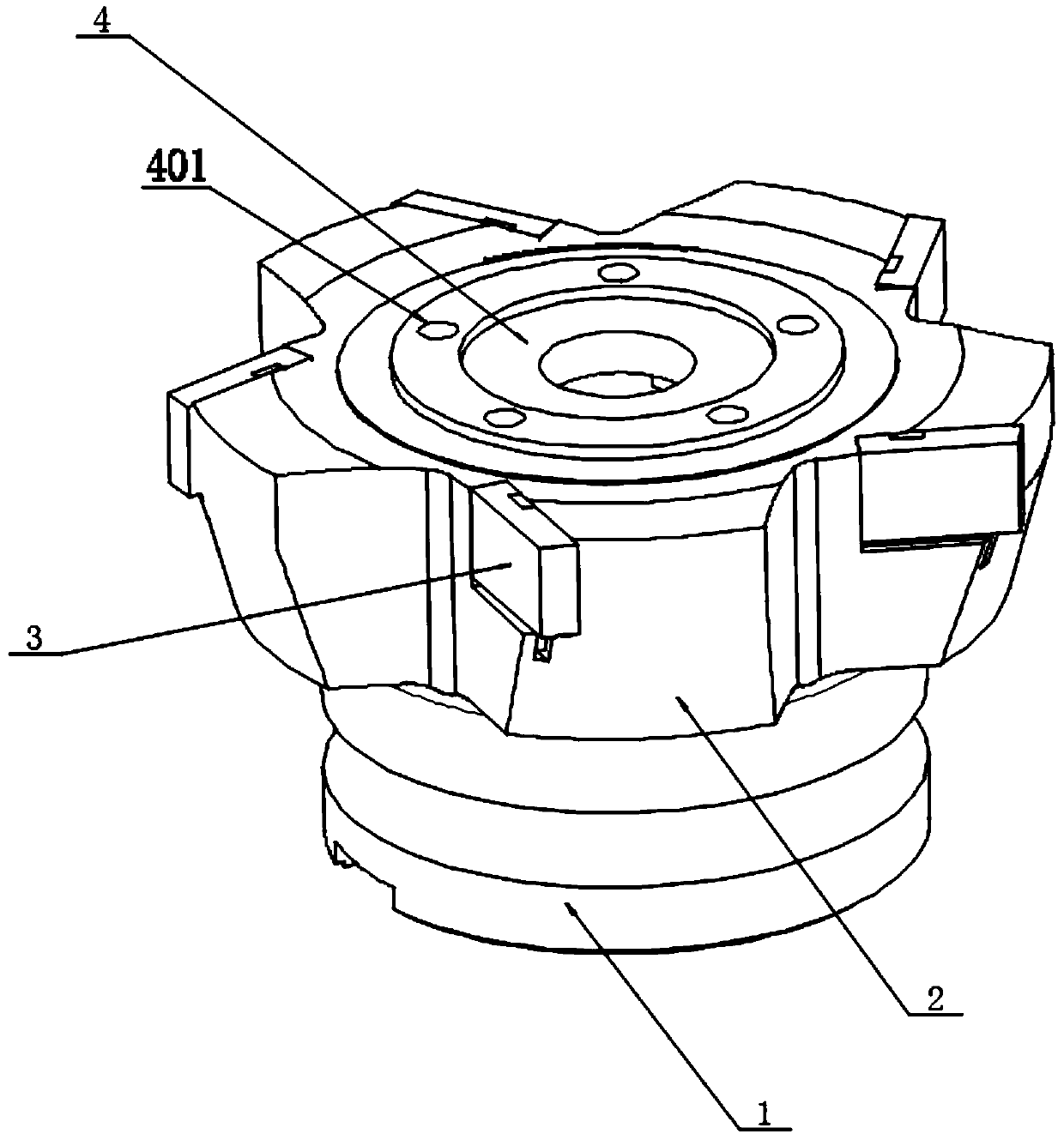
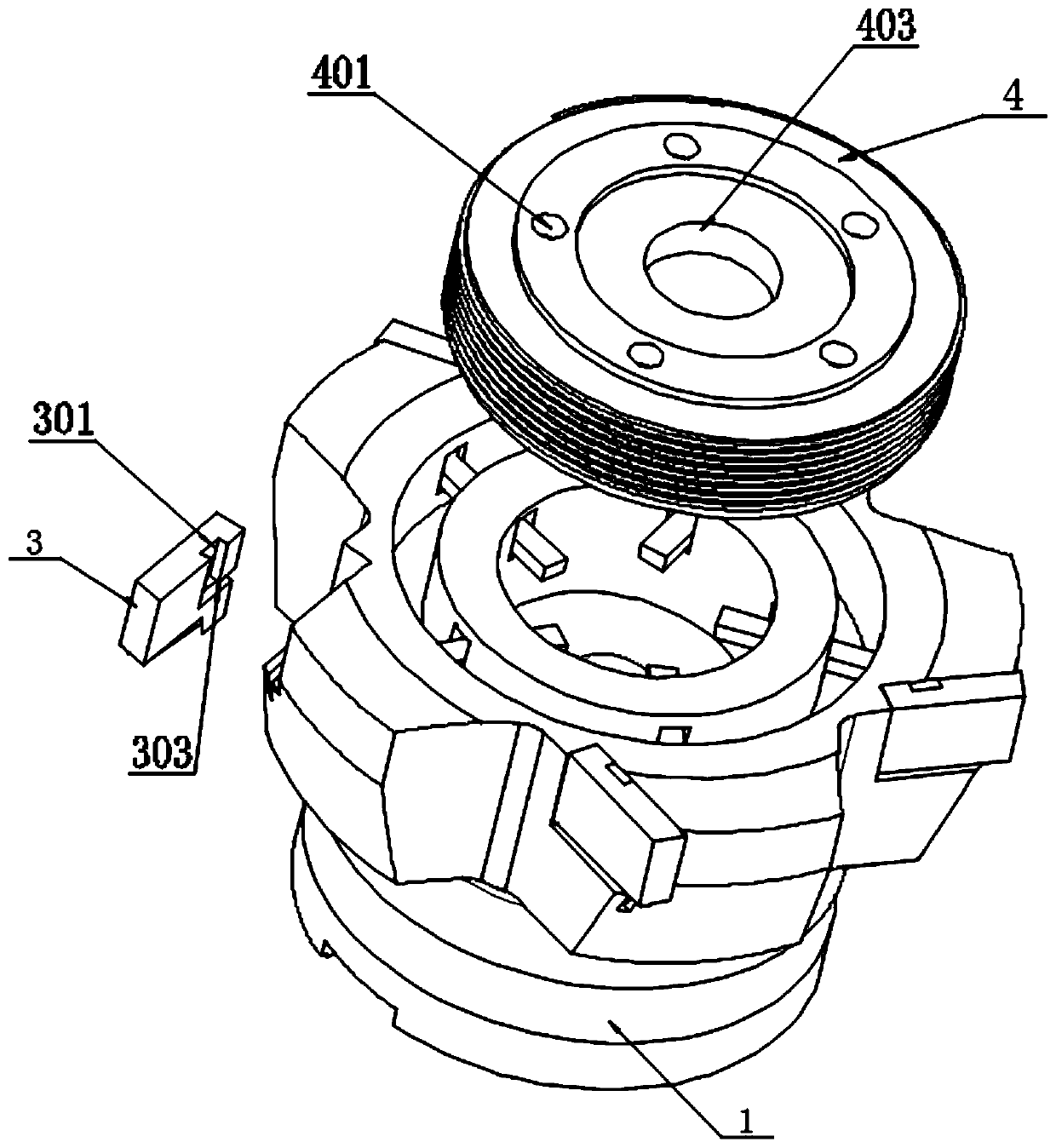
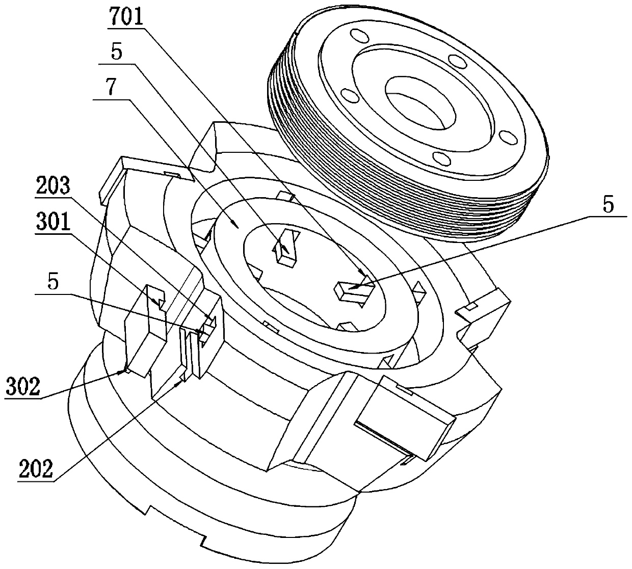
[0028] see Figure 1 to Figure 8 , an embodiment provided by the present invention: a CNC machine tool rotary cutter head for easy replacement of the cutter head, including a handle 1 and a fixed seat 4; The five-station tool holders 2 are also equipped with alloy material cutter heads 3, and a through hole is left in the middle of the five tool holders 2, and an inner ring seat 7 is machined on the inner ring of the through hole, and the inner ring seat An annular channel is formed between 7 and the knife seat 2, and a threaded ring 204 is provided on the inner wall of the annular channel, and five springs 6 are uniformly welded in the annular channel, and a spring ...


PUM


Abstract

The invention discloses a numerical control machine tool rotary cutter disc with cutter heads being replaced conveniently. The numerical control machine tool rotary cutter disc includes a cutter handle and a fixed seat; a cutter seat is arranged at the top end of the cutter handle, the cutter seat is of a five station type, and the cutter heads made of an alloy material are further installed on the five station cutter seats, through holes are formed in the middle positions of the cutter seats, inner ring seats are machined on inner rings of the through holes, and ring-shaped groove channels are formed between the inner ring seats and the cutter seats. Threaded rings are arranged on the inner walls of the ring-shaped groove channels, five springs are uniformly distributed and welded into the ring-shaped groove channels, pressing plates are welded to the top ends of the springs, inner ends of the pressing plates all extend inwards into the inner rings of the inner ring seats, and the ring-shaped fixed seats are arranged at the top of the cutter disc. Through the pressing plates uniformly arranged in the center of the cutter seats, the cutter heads can be press-fitted on the cutter seat stations at one time, and when the cutter heads are removed, the fixed seat rotates outwards, the L-shaped groove channels of the cutter heads are separated from the outer end heads of the pressingplates, so that the purpose of quickly removing and replacing the cutter heads in batch is achieved.

Description

technical field [0001] The invention relates to the technical field of rotary cutterhead structure, in particular to a rotary cutterhead of a numerical control machine tool which is convenient for replacing cutter heads. Background technique [0002] A CNC milling cutter is a rotating tool with one or more teeth for milling operations. When working, each knife tooth cuts off the allowance of the workpiece intermittently in turn. Milling cutters are mainly used for machining processes such as steps, grooves, forming surfaces and cutting off workpieces. [0003] For example, the application number CN201911077375.7 discloses a milling mechanism of CNC precision milling equipment based on rail welds, which relates to the technical field of peripheral milling cutter structure, and solves the problem of inconvenient maintenance and disassembly of existing CNC peripheral milling cutters. A milling cutter mechanism of a numerically controlled precision milling device based on rail...

Claims


Application Information

Patent Timeline
IPC IPC(8): B23C5/22B23C5/26
CPCB23C5/22B23C5/26
Inventor 林飞
Owner TAIZHOU BETTER TOOLS CO LTD
Learn More