Edge folding tool for front top light support of automotive trim ceiling

A technology for car interiors and lamp brackets, which is applied in the directions of feeding devices, positioning devices, storage devices, etc., can solve the problems of deformation, damage to the ceiling body, and high cost of use

Pending Publication Date: 2020-07-07
重庆市久满汽车内饰件有限公司
View PDF0 Cites 2 Cited by
  • Summary
  • Abstract
  • Description
  • Claims
  • Application Information

AI Technical Summary

Problems solved by technology

However, in the process of use, it is found that the hemming tooling of this method must be completely corresponding to the position of the mold during assembly, so that the hemming can be successfully folded, that is to say, the height of the metal frame and the mold must be matched. Therefore, not only the precision of the guide device of the mold and tooling is high, but the metal frame itself must also have high precision; it also puts forward high requirements for the operator's proficiency in operation, otherwise it will be easy during the assembly process of the metal frame. The hemming position of the bracket cannot be deformed as expected, so that the frame cannot be fastened to the ceiling body, causing the frame to be scrapped; it may even damage the ceiling body, causing greater losses
Moreover, in the prior art for the assembly mold of the metal bracket of the ceiling headlight of the automobile interior, one assembly mold can only be bent for the metal frame 1 of the same type and size, and if the mold is partially worn, it needs to be replaced as a whole, and the use cost high

Method used


Image

  • Edge folding tool for front top light support of automotive trim ceiling
  • Edge folding tool for front top light support of automotive trim ceiling
  • Edge folding tool for front top light support of automotive trim ceiling

Examples


no. 1 example

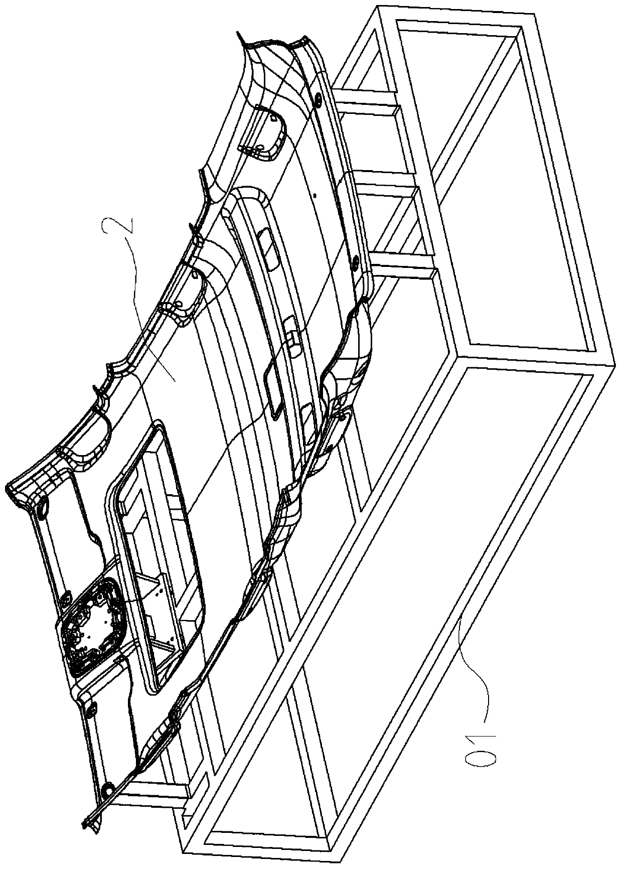
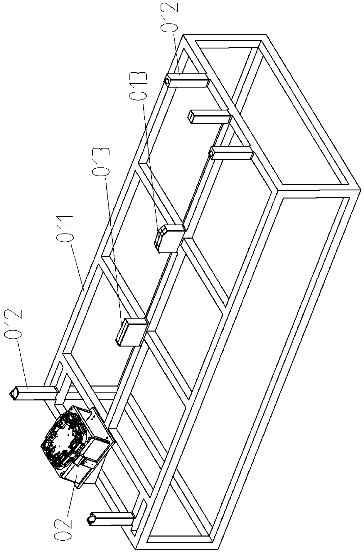
[0027] Including ceiling bracket 01, base 02 and push plate 03. Ceiling bracket 01 comprises base 011, support bar 012 and positioning block 013, and support bar 012 has several and is vertically fixed on the base 011, and positioning block 013 is welded with base 011 and adapts to the depression of ceiling body. The base 02 is located on the base 011 and is bolted to the base 011 through the tripod 04; the upper part of the base 02 is provided with a shaping module 05 and a hemming module 06, and the two sides of the base 02 are provided with ejection modules 07. The base 02 is provided with a through hole through which the push plate 03 can pass, and the push plate 03 can pass through the base 02 and vertically reciprocate. The shaping module 05 is arranged in a ring shape, and the upper surface of the shaping module 05 is provided with a first locking groove 051 for positioning, and the first locking groove 051 is used for positioning the metal frame 1 . The quantity of he...

Embodiment 2

[0031]In order to facilitate the installation of the present invention, the shaping module 05 is composed of a limit block 052 and a support block 053, the number of the support block 053 is the same as that of the hemming module 06, and the limit block 052 and the support block 053 are arranged at intervals. One side of the support block 053 is integrally provided with a connection platform 054 , and the support block 053 is bolted to the base 02 through the connection platform 054 . The bending part of the pressure block 063 is hinged with the support block 053 .

[0032] When installing before use, the support block can be connected to the hemming module first, and then the support block 053 and the hemming module 06 are respectively bolted to the base 02 and the push plate 03; when the support block 053 is connected to the base 02, the Just connect to the top of seat 02. And when one or several of the limiting block 052 and the supporting block 053 are worn, they can be r...

Embodiment 3

[0035] When the metal frame 1 has a certain radian, in order to ensure that the folding angle of the folding module is the same without replacing the connecting rod 062 (that is, the movement track and method during the bending process of the folding 3 are the same), it is necessary to make each pressing Block 063 opens at the same angle. Such as Figure 5 and Figure 10 As shown, in order to adapt to the metal frame 1 bent downwards at both ends, a groove 031 is provided on the push plate 03, and the connecting block is located in the groove 031. In the case of only replacing the shaping module 05 without replacing the connecting rod 062, the depth of the groove is adjusted according to the radian of the metal frame 1, so as to ensure that the turning angle of the hemming module 06 is the same. Because the push plate 03 is cheap, easy to process and easier to disassemble, one or several grooves 031 are processed on the push plate 03 according to the needs, and the depth of ...


PUM

PropertyMeasurementUnit
Hardnessaaaaaaaaaa

Abstract

The invention particularly relates to an edge folding tool for a front top light support of an automotive trim ceiling. The edge folding device comprises a ceiling support, a base and a push plate, wherein the upper part of the base is provided with a shaping module and an edge folding module, and the two sides of the base are provided with ejection modules; the push plate can penetrate through the base and reciprocate vertically; the shaping module is arranged in a ring-shaped mode; the number of the edge folding modules is the same as that of folded edges of the support, and each edge folding module comprises a connecting block, connecting rods and a pressing block which are sequentially hinged; and each pressing block is arranged in a V shape, the bending parts of the pressing blocks are hinged to the shaping module, one side of the bending part of each pressing block serves as a connecting part, the other side of each pressing block serves as a turning folding part, and each turning folding part is hinged to the connecting rods; the connecting blocks are fixedly connected with the push plate; and each ejection module is provided with a second clamping groove, and the ejection modules can reciprocate in the vertical direction. The edge folding tool for the front top light support of the automotive trim ceiling has the advantages that the assembly success rate is high, and the requirement for precision of a metal support is not high.

Description

technical field [0001] The invention relates to a hemming tool for an automobile ceiling, in particular to a hemming tool for a front dome light bracket of an automobile interior decoration ceiling. Background technique [0002] Commonly used metal brackets for headlights on ceilings in automotive interiors require fixed connection and assembly of the metal frame 1 and the ceiling body 2 . The inner edge of the metal frame is vertically provided with a plurality of folds 3 , and after the folds are turned 90°, the ceiling body is clamped between the folds and the metal frame, so that the metal frame 1 is fastened to the ceiling body 2 . At present, the assembly mold of the metal bracket of the ceiling headlight of the automobile interior is composed of accessories such as a base frame, upper and lower molds, cylinders, guide posts and guide sleeves. The upper mold of the mold is driven by the cylinder to press down, and the mold bends and deforms the connection between the ...

Claims


Application Information

Patent Timeline
IPC IPC(8): B21D35/00B21D19/00B21D7/16B21D43/00B21D7/00
CPCB21D7/00B21D7/16B21D19/00B21D35/003B21D43/003
Inventor 王贺友王文升李家付李云忠
Owner 重庆市久满汽车内饰件有限公司
Why Eureka
Try Eureka