Multi-stage soft charging control method and system for multi-level direct-current solid-state transformer
A technology of solid-state transformers and control methods, applied in control/regulation systems, converting DC power input to DC power output, adjusting electrical variables, etc., to achieve the effects of safe operation, stable charging, and reduced current peaks
- Summary
- Abstract
- Description
- Claims
- Application Information
AI Technical Summary
Problems solved by technology
Method used
Image
Examples
Embodiment 1
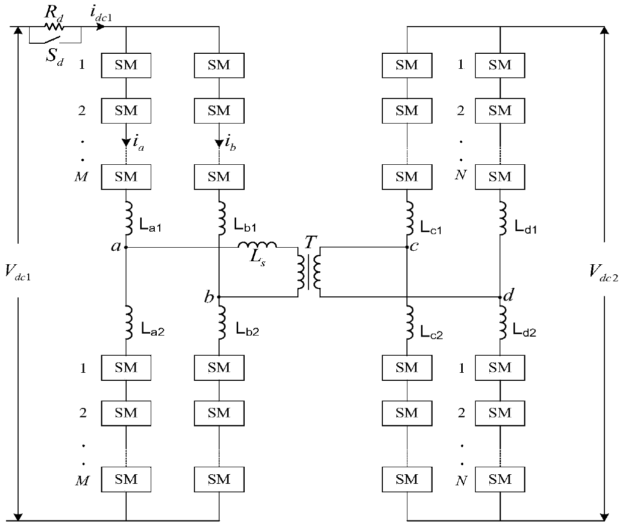
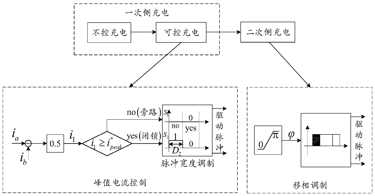
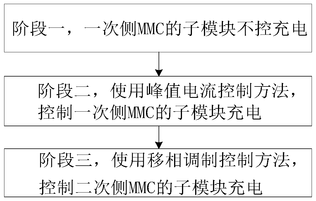
[0062] Such as figure 1 As shown, a multi-stage soft charge control method for a multi-level DC solid-state transformer, the modular multi-level DC solid-state transformer includes an input source V dc1 , the output source V dc2 , primary side MMC, secondary side MMC, current limiting resistor R d , the current limit switch S d , high-frequency transformer T; the leakage inductance of the high-frequency transformer T is L s ; The primary side MMC includes a plurality of sub-modules SM to form an H-bridge circuit; the secondary side MMC includes a plurality of sub-modules SM to form an H-bridge circuit; the primary-side MMC and the secondary-side MMC pass high frequency The transformer T is connected; the current limiting resistor R d with current limit switch S d After parallel connection, one end is connected to the primary side MMC, and the other end is connected to the input source V dc1 connection; the input source V dc1 is a DC source; the input source V dc1 Suppl...
Embodiment 2
[0104] Such as figure 1 As shown, a multi-level DC solid-state transformer multi-stage soft charge control system, the modular multi-level DC solid-state transformer includes an input source V dc1 , the output source V dc2 , primary side MMC, secondary side MMC, current limiting resistor R d , the current limit switch S d , high-frequency transformer T; the leakage inductance of the high-frequency transformer T is L s ; The primary side MMC includes a plurality of sub-modules SM to form an H-bridge circuit; the secondary side MMC includes a plurality of sub-modules SM to form an H-bridge circuit; the primary-side MMC and the secondary-side MMC pass high frequency The transformer T is connected; the current limiting resistor R d with current limit switch S d After parallel connection, one end is connected to the primary side MMC, and the other end is connected to the input source V dc1 connection; the input source V dc1 is a DC source; the input source V dc1 Supply powe...
PUM
 Abstract
Description
Claims
Application Information
 - R&D
- Intellectual Property
- Life Sciences
- Materials
- Tech Scout
- Unparalleled Data Quality
- Higher Quality Content
- 60% Fewer Hallucinations
Browse by: Latest US Patents, China's latest patents, Technical Efficacy Thesaurus, Application Domain, Technology Topic, Popular Technical Reports.
© 2025 PatSnap. All rights reserved.Legal|Privacy policy|Modern Slavery Act Transparency Statement|Sitemap|About US| Contact US: help@patsnap.com


