Hydraulic valve with valve element friction compensation function under centrifugal environment

A hydraulic valve and friction technology, applied in the field of hydraulic valves, can solve the problems of increasing the dead zone range, reducing the motion performance, slowing down the response speed, etc. effect of time

Pending Publication Date: 2020-07-03
杭州博力液控科技有限公司
View PDF0 Cites 1 Cited by
  • Summary
  • Abstract
  • Description
  • Claims
  • Application Information

AI Technical Summary

Problems solved by technology

[0002] When the hydraulic actuator system runs on the centrifuge as an airborne device, if the moving direction of the moving parts is not parallel to the direction of the centrifugal force, the contact force between the moving parts and the bearing parts will increase, resulting in an increase in the friction during the movement of the parts, thus reduced athletic performance
The hydraulic valve is the core control element of the hydraulic actuator system. After the internal main valve core is subjected to centrifugal force, relative movement occurs between the valve core and the valve sleeve or between the valve core and the valve body. The friction force will be greatly increased, and the existing hydraulic valves working in the centrifugal environment will have problems such as increased dead zone range, higher starting pressure, and slower response speed because the friction force cannot be compensated, and even cause the spool Seizure prevents the hydraulic system from working properly

Method used


Image

  • Hydraulic valve with valve element friction compensation function under centrifugal environment
  • Hydraulic valve with valve element friction compensation function under centrifugal environment
  • Hydraulic valve with valve element friction compensation function under centrifugal environment

Examples


Embodiment 1

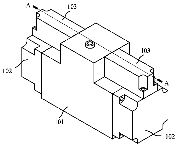
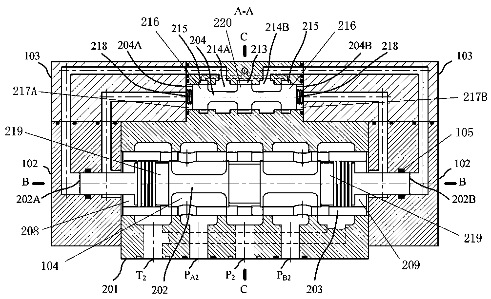
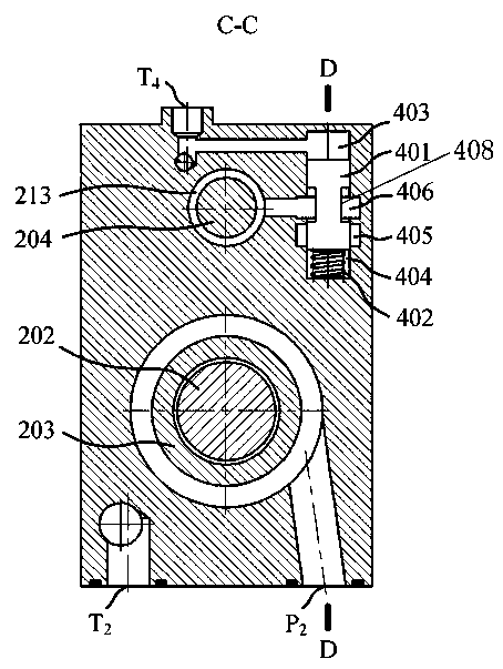
[0028] A hydraulic valve with spool friction compensation in a centrifugal environment, such as Figure 1~Figure 6 As shown, it includes valve body 201, main spool 202, reversing spool 204 and compensating spool 401, as figure 2 As shown, the valve body 201 is provided with a main cavity 104, a reversing cavity and a control cavity, and the main valve core 202 is slidably arranged in the main cavity 104; the left and right side walls of the reversing cavity are respectively provided with Return spring 218, reversing valve core 204 is slidably installed between two return springs 218, reversing valve core 204 is provided with reversing protrusion 220, and the outside of reversing protrusion 220 is provided with pressure cavity 213, and reversing protrusion 220 is close to and blocks the inner end of the pressure chamber 213, the length of the outer side of the reversing protrusion 220 is slightly longer than the length of the inner end of the pressure chamber 213, and the reve...

Embodiment 2

[0034] The difference from Embodiment 1 is that it also includes a pilot valve 602, such as figure 2 As shown, the reversing valve core 204 divides the reversing cavity into a left end cavity 217A and a right end cavity 217B. The left and right sides of the main valve core 202 are respectively provided with annular protrusions 219, and the annular protrusions 219 separate the main cavity. 104 is divided into a left cavity 208 and a right cavity 209, the left cavity 208 communicates with the left end cavity 217A through a flow channel, and the right cavity 209 communicates with the right end cavity 217B through a flow channel, as Figure 5 As shown, the left cavity 208 and the right cavity 209 communicate with different control ports of the pilot valve respectively, and the control port of the pilot valve 602 includes the first connection port P of the pilot valve. A3 and the second port of the pilot valve P B3 . The pilot valve 602 is used to assist in controlling the main ...


PUM


Abstract

The present invention provides a hydraulic valve with a valve element friction compensation in a centrifugal environment. The hydraulic valve comprises a valve body, a main valve element, a reversingvalve element and a compensation valve element, during a static state, the compensation valve element blocks an oil supply cavity, illustration is carried out by taking the centrifugal environment rotating to the left side as the example, the compensation valve element is displaced under the action of centrifugal force, a sharp edge throttling port is generated between a connecting groove and theoil supply cavity and communicates with the oil supply cavity and an adjusting cavity, high pressure oil enters a pressure cavity along the adjusting cavity from the oil supply cavity, the larger thecentrifugal force is, the larger the sharp edge throttling port is, the larger the pressure in the pressure cavity is, the reversing valve element moves to the right under the action of inertia, a left reversing cavity communicates with the pressure cavity, the high pressure oil passes from the left reversing cavity to the left end face of the main valve element, the oil pressure in the left end face of the main valve element is increased, so that movement to the right of the main valve element is accelerated, the direction is opposite to the direction of the friction force applied to the mainvalve element, then the friction force is compensated, and the moving time of the main valve element is shortened.

Description

technical field [0001] The invention relates to the field of hydraulic valves, in particular to a hydraulic valve for compensating valve core friction force in a centrifugal environment. Background technique [0002] When the hydraulic actuator system runs on the centrifuge as an airborne device, if the moving direction of the moving parts is not parallel to the direction of the centrifugal force, the contact force between the moving parts and the bearing parts will increase, resulting in an increase in the friction during the movement of the parts, thus Reduced athletic performance. The hydraulic valve is the core control element of the hydraulic actuator system. After the internal main valve core is subjected to centrifugal force, relative movement occurs between the valve core and the valve sleeve or between the valve core and the valve body. The friction force will be greatly increased, and the existing hydraulic valves working in the centrifugal environment will have p...

Claims


Application Information

Patent Timeline
Patent Type & Authority Applications(China)
IPC IPC(8): F15B13/02F16K11/07F16K31/12
CPCF15B13/026F16K11/07F16K31/12
Inventor 宫华胜
Owner 杭州博力液控科技有限公司
Why Eureka
Try Eureka