Eureka AIR delivers breakthrough ideas for toughest innovation challenges, trusted by R&D personnel around the world.

Underground gas cut monitoring system based on ultrasonic waves

A monitoring system, ultrasonic technology, applied in the field of oil and gas drilling, can solve the problems of low gas invasion monitoring accuracy and unreliable results, and achieve the effects of reliable and accurate gas invasion data, faster flow velocity, and reduced cross-sectional area

Active Publication Date: 2020-07-03
CHINA UNIV OF PETROLEUM (EAST CHINA)
View PDF10 Cites 8 Cited by
  • Summary
  • Abstract
  • Description
  • Claims
  • Application Information

AI Technical Summary

Problems solved by technology

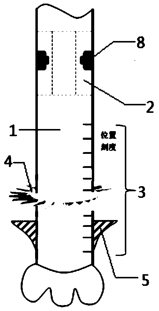
[0004] The purpose of the present invention is to solve the defects of the existing downhole ultrasonic monitoring gas invasion method that it is difficult to grasp the gas fraction of the entire annular space due to the small ultrasonic monitoring information window and the monitoring results are affected by rock debris, resulting in low gas invasion monitoring accuracy and unreliable results. An ultrasonic-based downhole gas intrusion monitoring system, which can not only effectively separate downhole gas intrusion gas and cuttings, eliminate the impact of cuttings on gas intrusion monitoring, but also make the gas intrusion gas in the entire annulus as concentrated as possible The effective monitoring window near the drill pipe solves the problem that the current downhole monitoring method of gas intrusion is limited by the space of the monitoring window and the impact of cuttings, and greatly improves the timeliness, accuracy and reliability of gas intrusion monitoring

Method used


Image

  • Underground gas cut monitoring system based on ultrasonic waves
  • Underground gas cut monitoring system based on ultrasonic waves
  • Underground gas cut monitoring system based on ultrasonic waves

Examples


Embodiment 1

[0028] The gas intrusion monitoring during the drilling process of a certain well is taken as an example to introduce. The relevant specific parameters of the well are as follows: well depth 4280m, drill pipe speed 120r / min, drilling fluid density 1.6g / m 3 , displacement 20L / s, gas intrusion gas is CH 4 , The initial viscosity of the drilling fluid is 55Pa·s, the reservoir pressure is 68MPa, the geothermal gradient is 0.0463°C / m, the formation permeability is 50md, and the formation porosity is 30%.

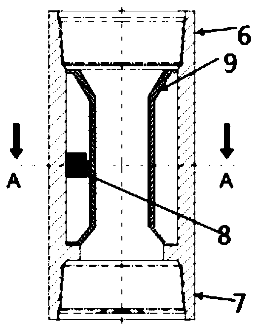
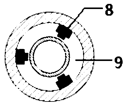
[0029] The ultrasonic-based downhole gas intrusion monitoring system includes an ultrasonic gas intrusion monitoring device 2 fixed on the drill pipe 1, and an annular air-solid separation device 3 located below the ultrasonic air intrusion monitoring device 2. The annular air-solid separation device 3 includes a turbine 4 and a gas-solid pre-separation device 5 fixed on the drill pipe 1 sequentially from top to bottom. The distance between the turbine 4 and the top of the gas-...


PUM

PropertyMeasurementUnit
viscosityaaaaaaaaaa
diameteraaaaaaaaaa
thicknessaaaaaaaaaa

Abstract

The invention belongs to the technical field of oil and gas drilling and particularly relates to an underground gas cut monitoring system based on ultrasonic waves. The monitoring system comprises anultrasonic gas cut monitoring device fixed on a drill rod and an annular gas-solid separation device located below the ultrasonic gas cut monitoring device; and the annular gas-solid separation devicecomprises a turbine and a gas-solid pre-separation device which are sequentially fixed on the drill rod from top to bottom. The underground gas cut monitoring system based on ultrasonic waves can effectively separate gas cut gas and rock debris in the well, eliminate the influence of the rock debris on gas cut monitoring, and also can enable the gas cut gas in the whole annular space to be concentrated in an effective monitoring window near the drill rod as far as possible, thereby solving the problem that a current underground gas cut monitoring method is limited by the space of the monitoring window and influenced by the rock debris, and greatly improving the timeliness, precision and reliability of gas cut monitoring.

Description

technical field [0001] The invention belongs to the technical field of oil and gas drilling, and in particular relates to an ultrasonic-based downhole gas invasion monitoring system. Background technique [0002] In the exploration and development of deep water and deep oil and gas resources, due to the lack of accurate prediction and monitoring information on the deep water environment, deep formations and working conditions, the risk of downhole complex accidents during the drilling process has increased significantly, among which blowout is a complex, A major accident that is extremely harmful and difficult to avoid and deal with once it occurs. Early monitoring of gas kick has become one of the key technical means to avoid blowout and implement effective well control. [0003] At present, the commonly used early monitoring methods for gas invasion and overflow are mainly the drilling fluid pool increment method and the outlet flow difference method, but for deep water a...

Claims


Application Information

Patent Timeline
Patent Type & Authority Applications(China)
IPC IPC(8): E21B47/107E21B47/017B01D45/14
CPCB01D45/14Y02E10/10
Inventor 许玉强管志川刘永旺廖华林史玉才宋洵成
Owner CHINA UNIV OF PETROLEUM (EAST CHINA)
Why Eureka
Eureka Blog
Learn More