Stamping die for facilitating waste discharge

A technology for stamping dies and waste materials, which is applied in the field of stamping dies that facilitate the discharge of waste materials. It can solve the problems of unsatisfactory automatic production, low cleaning efficiency, and high risk factor of operation, so as to improve operation safety, high work efficiency, and convenient and fast operation. Effect

Inactive Publication Date: 2020-07-03
李富鸿
View PDF0 Cites 0 Cited by
  • Summary
  • Abstract
  • Description
  • Claims
  • Application Information

AI Technical Summary

Problems solved by technology

[0003] During the stamping process using the stamping die, some waste materials will be generated inside the lower die. In order to ensure the accuracy of the upper die and the lower die during the stamping process and prolong the service life of the die, these waste materials need to be cleaned up in time. At present, most stamping The waste in the operation is basically discharged and cleaned manually, the operation risk factor is high, and the cleaning efficiency is relatively low, which cannot meet the needs of automated production

Method used


Image

  • Stamping die for facilitating waste discharge
  • Stamping die for facilitating waste discharge
  • Stamping die for facilitating waste discharge

Examples


Embodiment 1

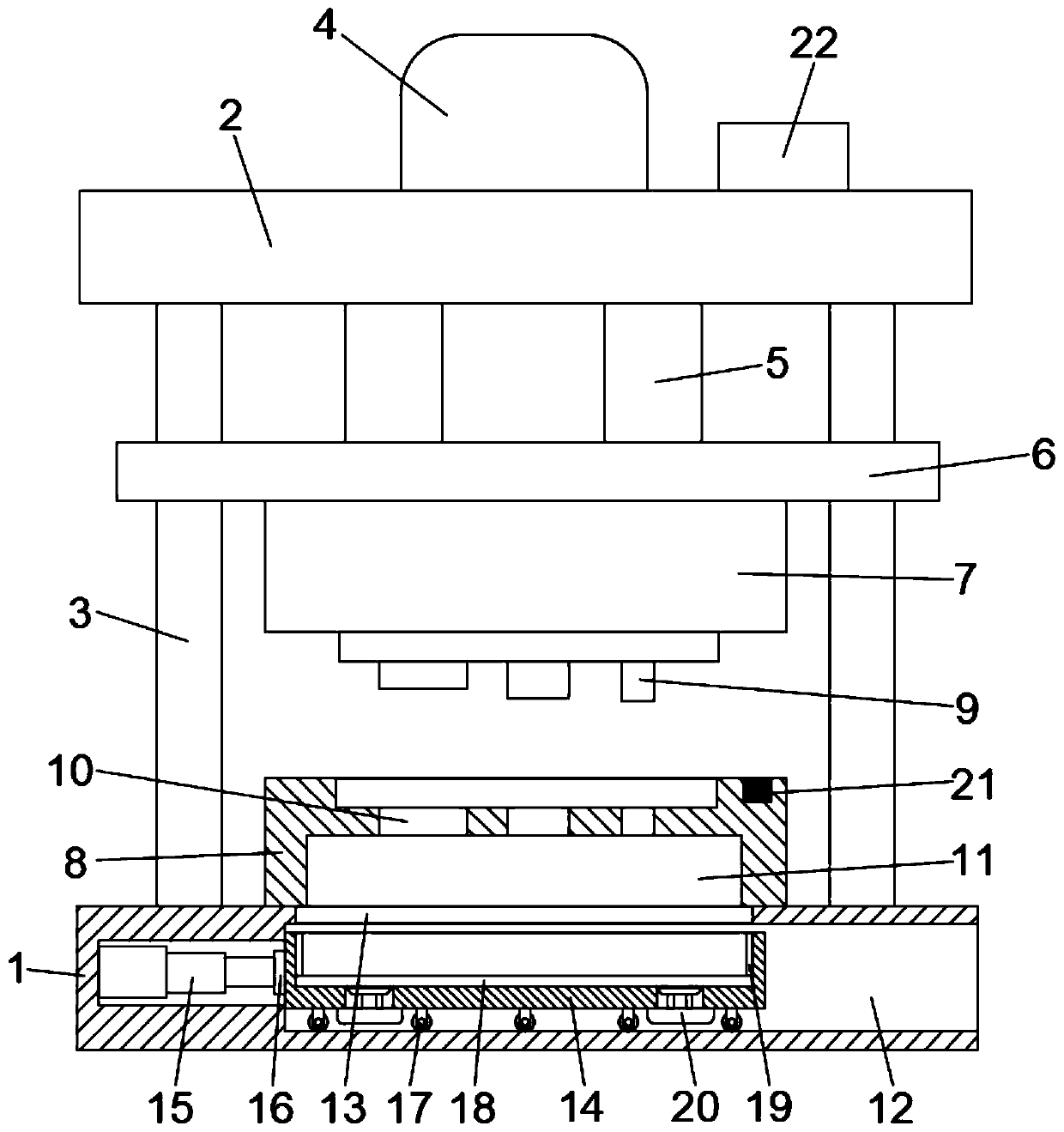
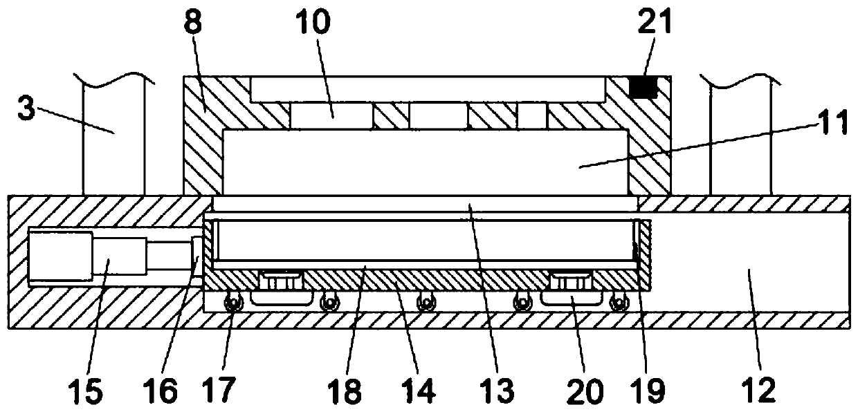
[0024] see Figure 1-2 , a stamping die to facilitate the discharge of waste materials, including a base 1 and a top plate 2, a support column 3 is vertically fixed between the base 1 and the top plate 2, a hydraulic press 4 is installed on the top plate 2, and the lower end of the hydraulic press 4 is connected to There is a telescopic cylinder 5 vertically penetrating the top plate 2. The bottom of the telescopic cylinder 5 is fixed with a lifting plate 6 slidingly sleeved on the support column 3. An upper mold 7 is installed on the lower end of the lifting plate 6. On the base 1 The end face is equipped with a lower mold 8, the upper mold 7 is provided with a stamping block 9, the lower mold 8 is provided with a punching hole 10 corresponding to the stamping block 9, and the bottom of the lower mold 8 is provided with a punching hole 10 connected to the empty slot 11; the base 1 is provided with a chamber 12, the top of the chamber 12 is provided with an opening 13 communic...

Embodiment 2

[0034] A stamping die for facilitating waste discharge, comprising a base 1 and a top plate 2, a support column 3 is vertically fixed between the base 1 and the top plate 2, a hydraulic press 4 is installed on the top plate 2, and the lower end of the hydraulic press 4 is connected with The telescopic cylinder 5 vertically runs through the top plate 2, the bottom of the telescopic cylinder 5 is fixed with a lifting plate 6 slidingly sleeved on the support column 3, the lower end of the lifting plate 6 is equipped with an upper mold 7, and the upper end of the base 1 is A lower mold 8 is installed, the upper mold 7 is provided with a stamping block 9, the lower mold 8 is provided with a punching hole 10 corresponding to the stamping block 9 one by one, and the bottom of the lower mold 8 is provided with a punching hole 10 A connected hollow groove 11; a chamber 12 is provided in the base 1, an opening 13 communicating with the hollow groove 11 is arranged above the chamber 12, a...


PUM


Abstract

The invention discloses a stamping die for facilitating waste discharge. The stamping die comprises a base and a top plate, wherein a lower die is arranged on the upper end face of the base; a punching hole is formed in the lower die; an empty groove which communicates with the punching hole is formed in the bottom of the lower die; a cavity is formed in the base; a collection box is arranged in the cavity; a push-pull device is fixedly arranged on the side wall of the cavity; a slide rail is vertically arranged on the inner wall of the collection box; a jacking plate is clamped in the slide rail in a sliding way; a sweeping assembly is arranged on the jacking plate; a jacking mechanism is arranged around the bottom of the collection box; a counter is arranged on the upper end face of thelower die; and a controller is arranged on the upper end face of the jacking plate. According to the stamping die for facilitating waste discharge, the collection box is pushed out automatically aftera certain number of stamping, so that the discharge and cleaning of waste are facilitated. The jacking mechanism and the sweeping assembly are arranged in the collection box, so that operation is convenient and rapid; manual cleaning is not needed; and high working efficiency and high security are achieved.

Description

technical field [0001] The invention relates to the technical field of stamping dies, in particular to a stamping die which facilitates the discharge of waste materials. Background technique [0002] The stamping die is a special process equipment for processing materials into parts or semi-finished products in the cold stamping process. The existing stamping die includes an upper die and a lower die. The staff can design the shape of the upper die and the lower die according to the needs. A hydraulic device is set above the upper die, and the material is placed on the upper surface of the lower die, and the upper die is punched downward under the action of the hydraulic device, and then the required parts are obtained. [0003] During the stamping process using the stamping die, some waste materials will be generated inside the lower die. In order to ensure the accuracy of the upper die and the lower die during the stamping process and prolong the service life of the die, t...

Claims


Application Information

Patent Timeline
Patent Type & Authority Applications(China)
IPC IPC(8): B21D37/12B21D43/20B21D45/04B21C51/00
CPCB21C51/00B21D37/12B21D43/20B21D45/04
Inventor 李富鸿
Owner 李富鸿
Why Eureka
Try Eureka