Manufacturing installation for producing winding bar for electric motor, and method for producing winding bar

A technology for manufacturing equipment and winding wires, applied in the field of manufacturing equipment, can solve problems such as time-consuming and high investment costs, and achieve the effect of short cycle time and high processing speed

Inactive Publication Date: 2020-06-30
MIBA AUTOMATION SYST GES
View PDF5 Cites 0 Cited by
  • Summary
  • Abstract
  • Description
  • Claims
  • Application Information

AI Technical Summary

Problems solved by technology

[0003] The methods known from the prior art for removing the insulation of a winding bar blank or a winding bar have the disadvantage that they are time-consuming and entail high investment costs

Method used


Image

  • Manufacturing installation for producing winding bar for electric motor, and method for producing winding bar
  • Manufacturing installation for producing winding bar for electric motor, and method for producing winding bar
  • Manufacturing installation for producing winding bar for electric motor, and method for producing winding bar

Examples


Embodiment Construction

[0069] First of all, it should be confirmed that, in the different described embodiments, the same components have the same reference numerals or the same component names, and the disclosure contained in the entire specification can be reasonably transferred to the same reference numerals or the same component names. same parts. The position descriptions used in the description, such as eg top, bottom, side, etc., refer to the current description and the figures shown and can be appropriately transferred to the new position in the event of a change of position.

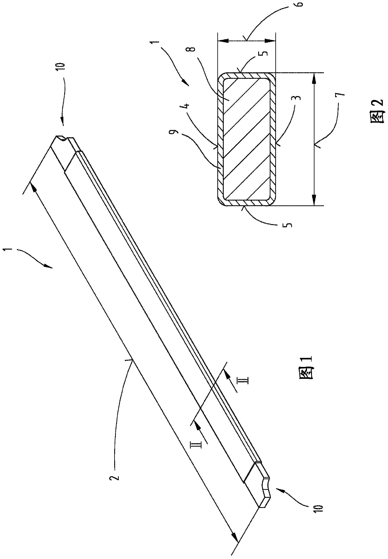
[0070] figure 1 A perspective view is shown of a winding bar 1 used to manufacture windings in electric machines. The use of winding bars 1 in electric machines is described in DE 10 2015 217 922 A1. The winding bar 1 has a bar length 2, which can be selected differently according to the specifications of the motor. In particular, it is also conceivable that the winding bars 1 for the same electrical machine can ha...


PUM


Abstract

The invention relates to a manufacturing installation (11) for producing a winding bar (1) for an electric motor, wherein the manufacturing installation (11) is designed for processing a winding bar blank (12) which has a core (8) composed of electrically conductive material and an insulating layer (9) which sheathes the core (8). The manufacturing installation (11) comprises an insulation-stripping apparatus (19) which is designed to partially remove the insulating layer (9) from a main surface (3) and a covering surface (4) of the winding bar blank (12), wherein the winding bar blank (12) can be guided through the insulation-stripping apparatus (19) in the production direction (20). The insulation-striping apparatus (19) has a machining tool (41) for mechanically removing the insulatinglayer (9) of the winding bar blank (12).

Description

technical field [0001] The invention relates to a manufacturing apparatus for manufacturing winding bars for electric machines, which is configured for processing winding bar blanks, and a method for manufacturing winding bars for electric machines. Background technique [0002] A winding bar is known from DE 10 2015 217 922 A1, which is inserted into the laminated core of an electric machine. The plurality of winding bars constitute the windings of the motor in a state of being electrically connected to each other. The winding bars are in the form of rods and are electrically connected to one another at their ends in order to form the winding. In addition, the individual winding bars have an encapsulated insulating layer. It is known from the prior art that the insulating layer can be partially burned off by means of a laser. [0003] The methods known from the prior art for removing the insulating layers of winding bar blanks or winding bars have the disadvantage that t...

Claims


Application Information

Patent Timeline
Patent Type & Authority Applications(China)
IPC IPC(8): H02K15/04
CPCB26D3/16H02K15/0421
Inventor A·福克纳M-M·普里莫拉克D·谢瑞
Owner MIBA AUTOMATION SYST GES
Why Eureka
Try Eureka