
Anti-electric-shock system for fluorescent lamp mounting

An anti-electric shock and fluorescent lamp technology, which is applied to the safety devices, lighting devices, lighting devices, etc. of lighting devices, can solve the problems of loose lamp tubes, reduced heat dissipation performance of lamp tubes, shaking of lamp sockets, etc., so as to prevent excessive temperature from being burned Damage, improve heat dissipation performance, prevent the effect of lamp falling

Pending Publication Date: 2020-06-30
吴朋伟
View PDF4 Cites 1 Cited by
  • Summary
  • Abstract
  • Description
  • Claims
  • Application Information

AI Technical Summary

Problems solved by technology

[0003] 1. Because people do not know whether the switch is on or off before installing the lamp tube, if people install the lamp tube, if the switch is not turned off in advance, it is easy to get an electric shock, and it is also easy to cause an electric shock when the lamp tube is not completely installed. When it is good, the lamp tube is suddenly energized and burns out the lamp tube;
[0004] 2. When the fluorescent lamp is used for a long time, a large amount of dust will adhere to the lamp tube. The accumulation of more and more dust will easily affect the brightness of the lamp tube, reduce the heat dissipation performance of the lamp tube, and easily burn out the lamp tube. If the dust is manually cleaned, people need to climb to a high place to wipe the lamp tube with a rag. The lamp tube is relatively fragile. If the force is not appropriate, the lamp tube is easy to break, and it is also dangerous for people to climb to a high place;
[0005] 3. In many places, such as school classrooms and other places, the lamp holders of fluorescent lamps are hung from the ceiling by long wires. Once the wind blows, it is easy to shake the lamp holders, loosen the lamp tubes, and make the lamps The tube falls, which is dangerous

Method used


Image

  • Anti-electric-shock system for fluorescent lamp mounting
  • Anti-electric-shock system for fluorescent lamp mounting

Examples


Embodiment Construction

[0020] The following will clearly and completely describe the technical solutions in the embodiments of the present invention with reference to the accompanying drawings in the embodiments of the present invention. Obviously, the described embodiments are only some, not all, embodiments of the present invention.

[0021] In describing the present invention, it should be understood that the terms "upper", "lower", "front", "rear", "left", "right", "top", "bottom", "inner", " The orientation or positional relationship indicated by "outside", etc. is based on the orientation or positional relationship shown in the drawings, and is only for the convenience of describing the present invention and simplifying the description, rather than indicating or implying that the referred device or element must have a specific orientation, so as to Specific orientation configurations and operations, therefore, are not to be construed as limitations on the invention.

[0022] refer to Figure ...


PUM


Abstract

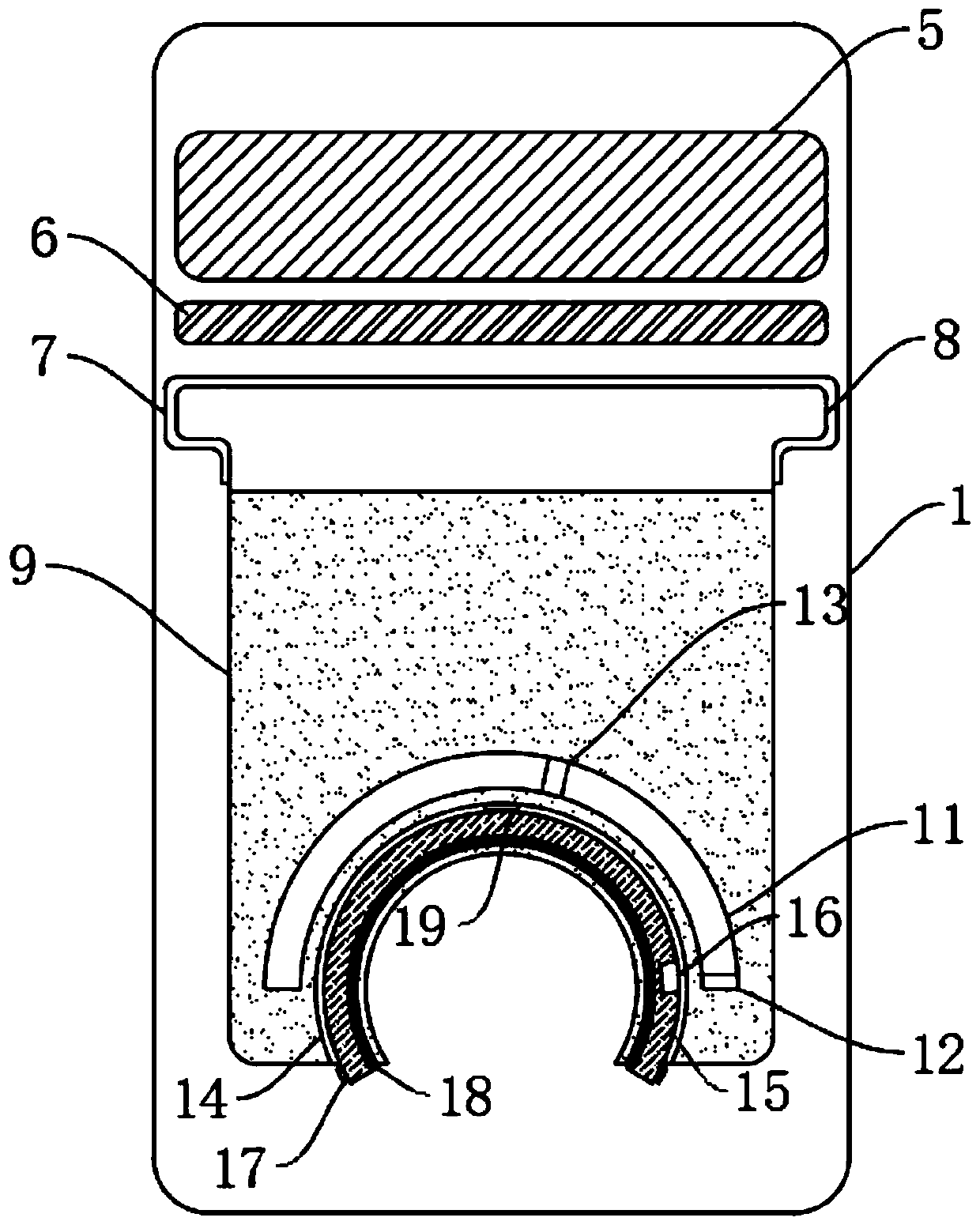
The invention discloses an anti-electric-shock system for fluorescent lamp mounting. The anti-electric-shock system comprises a lamp holder. The lamp holder is of an inverted U-shaped structure. Two opposite mounting seats are arranged on the two sides of the lamp holder. Two anti-electric-shock mechanisms are arranged on the side wall of the lamp holder. Each anti-electric-shock mechanism comprises a control panel arranged on the side wall of the lamp holder. A mounting groove is formed in the lower wall of each control panel. An arc groove is formed in the lower wall of each control panel. An arc plate capable of sliding is arranged in each arc groove. A limiting mechanism used for preventing the corresponding arc plate from falling off is arranged in each arc groove. An arc cavity is formed in each control panel. The position, close to the right end, of the inner wall of each arc cavity is in sliding connection with a moving magnet. The position, close to the middle, of the inner wall of each arc cavity is fixedly connected with an electromagnet. The heteropoles of the electromagnets and the moving magnets attract each other. The electromagnets are electrically connected with acircuit in the lamp holder. By means of the anti-electric-shock system, the situation that electric shocks happen when people mount lamp tubes when switches are turned on can be avoided, the brightness of lamp tubes can be guaranteed, and the heat radiation performance of lamp tubes can be improved.

Description

technical field [0001] The invention relates to the technical field of lamps, in particular to an electric shock prevention system for fluorescent lamp installation. Background technique [0002] Fluorescent lamps are often used in people's daily life. The lamp tube of the fluorescent lamp is a slender cylindrical shape. Install the two ends of the lamp tube on the lamp holder and make contact with the conductive contact piece, and then it can be used normally. However, The existing lamp holders have the following problems: [0003] 1. Because people do not know whether the switch is on or off before installing the lamp tube, if people install the lamp tube, if the switch is not turned off in advance, it is easy to get an electric shock, and it is also easy to cause an electric shock when the lamp tube is not completely installed. When it is good, the lamp tube is suddenly energized and burns out the lamp tube; [0004] 2. When the fluorescent lamp is used for a long time,...

Claims


Application Information

Patent Timeline
IPC IPC(8): F21V21/00F21V25/00F21V33/00B08B1/00B08B5/02
CPCF21V21/00F21V25/00F21V33/00B08B5/02B08B1/143
Inventor 吴朋伟
Owner 吴朋伟
Learn More