Modular assembling method of steel box girder bridge

A steel box girder, modular technology, applied in the direction of bridges, bridge construction, bridge materials, etc., can solve the problems of affecting the safety of bridge structures, delaying construction progress, increasing construction costs, etc., to improve construction efficiency and quality, and accurate spatial location , The effect of reducing the difficulty of construction

Active Publication Date: 2020-06-30
CHINA MCC5 GROUP CORP
View PDF17 Cites 7 Cited by
  • Summary
  • Abstract
  • Description
  • Claims
  • Application Information

AI Technical Summary

Problems solved by technology

The traditional steel box girder bridge assembly method is to assemble symmetrically from the center line to both sides in the horizontal direction, and then weld symmetrically from the center line to both sides in the horizontal direction, so as to reduce the lateral welding deformation of the steel box girder bridge; the above method has the following disadvantages: 1. When assembled symmetrically from the center line to both sides in the horizontal direction, the cumulative assembly deviation occurs from the center line to both sides. The anchor boxes on both sides are far away from the center line, and the cumulative position deviation is also large, but there are supports or cables at the anchor boxes. To support the weight of the entire bridge, the excessive deviation of the position of the anchor box will cause the load-bearing system of the bridge to fail to meet the design requirements, thereby affecting the structural safety of the bridge
The second is that the weight of each section of the steel box girder bridge is relatively large, and the symmetrical hoisting from the center line to both sides will cause the large crane to move back and forth to hoist the steel box girder, reducing the working time of the crane, which is not only prone to safety accidents, but also Seriously delay the construction schedule and increase construction costs, which are undesirable for those skilled in the art

Method used


Image

  • Modular assembling method of steel box girder bridge
  • Modular assembling method of steel box girder bridge
  • Modular assembling method of steel box girder bridge

Examples


Embodiment Construction

[0036] The structure of the present invention will be further described below in conjunction with the accompanying drawings and specific embodiments, but it is not intended as a limitation of the present invention.

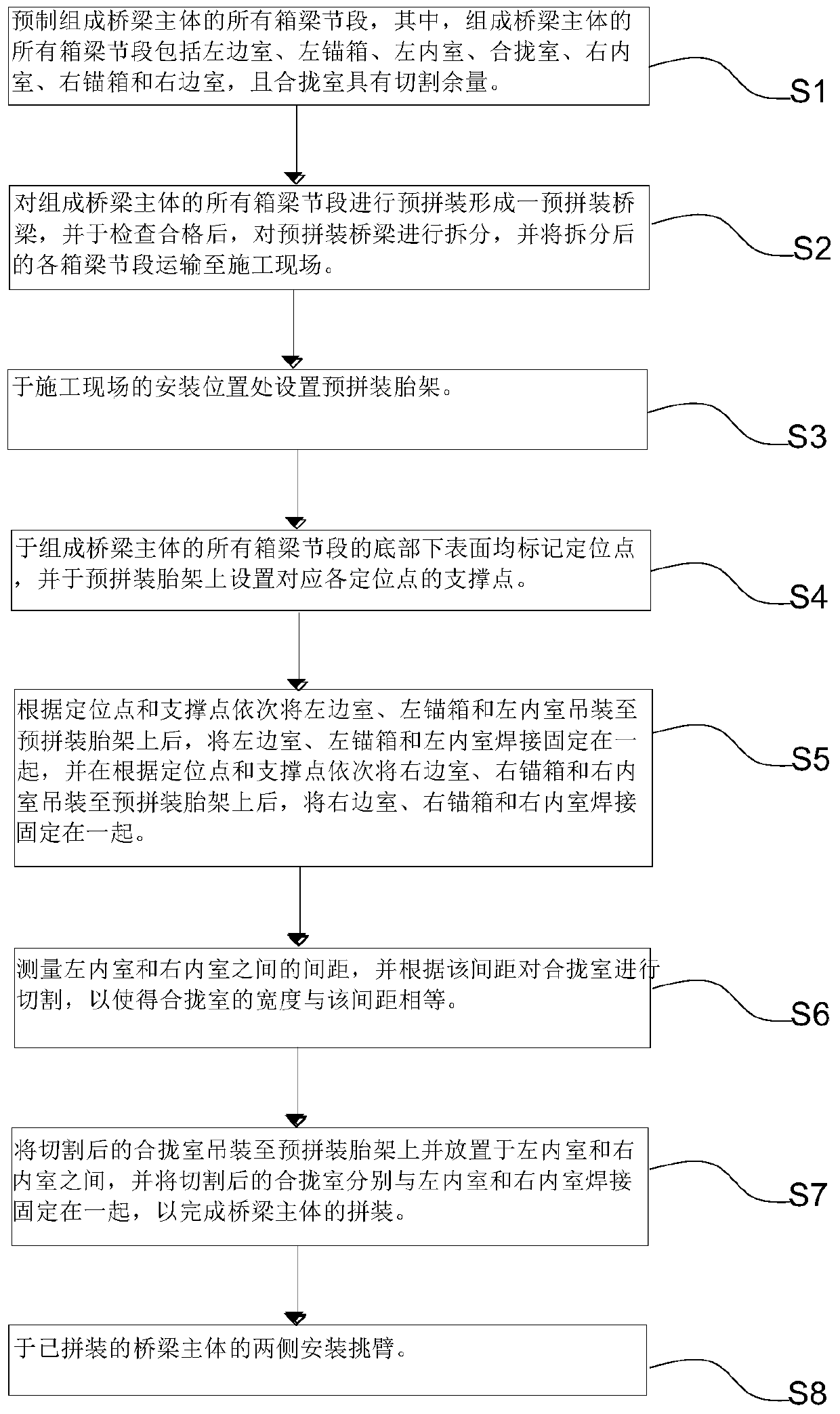
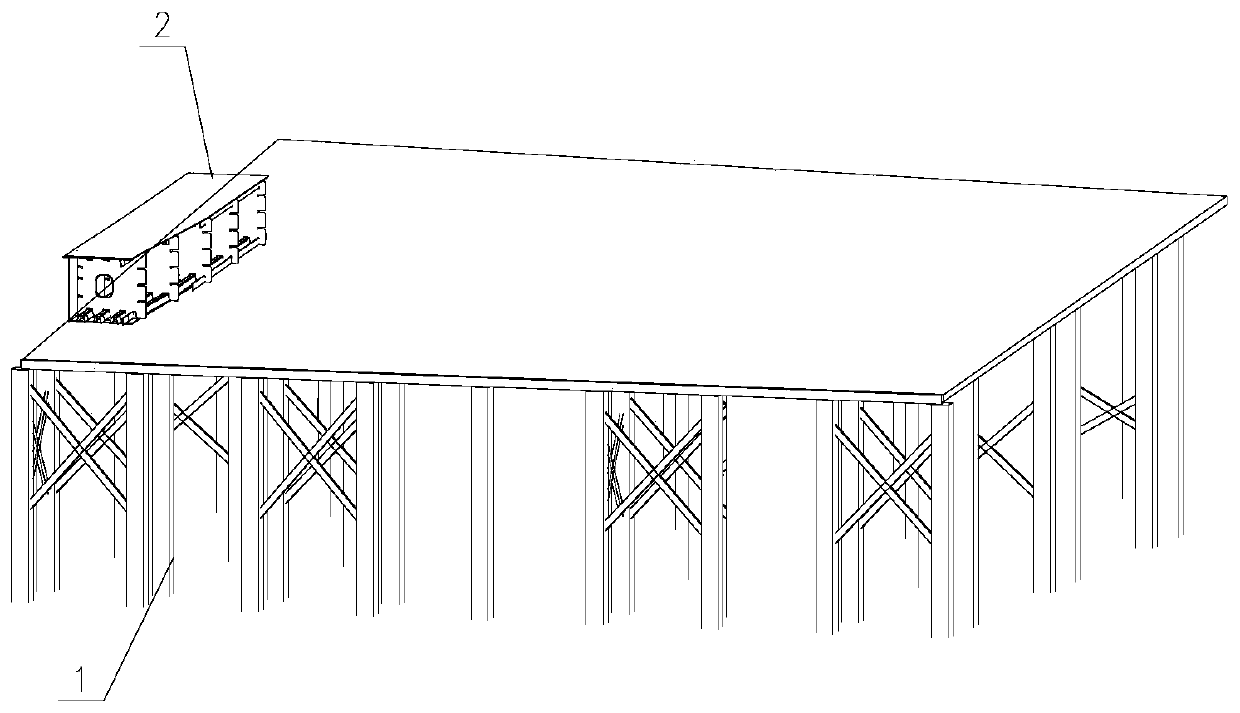
[0037] Such as Figure 1~5 As shown, the present invention discloses a modular assembly method of a steel box girder bridge. The steel box girder bridge includes a bridge body in the middle and pick arms (respectively left pick arm 10 and right pick arm 9) positioned at both sides of the bridge body. ), specifically, the method includes the following steps:

[0038] Step S1, prefabricating all the box girder segments that make up the main body of the bridge, specifically, all the box girder segments that make up the main body of the bridge include the left chamber 2, the left anchor box 3, the left inner chamber 4, and the closing chamber 8 (that is, the inner chamber), right inner chamber 7, right anchor box 6 and right chamber 5, and the closing chamber 8 has a...


PUM


Abstract

The invention relates to the technical field of steel structure bridge construction, in particular to a steel box girder bridge modular assembling method. All box girder sections of a bridge body forming the steel box girder bridge are prefabricated in a factory, and the cutting allowance of a middle closure chamber is reserved; after all the box girder sections are pre-assembled in a factory andthe qualified box girder sections are checked out, in the construction site, the steel box girder bridge is transversely assembled from the side chambers to the middle chambers, folded in the middle line and finally hoisted with the cantilever arm, so that the spatial position accuracy of the anchor box can be ensured, the crane displacement is reduced, the construction difficulty is reduced, theconstruction safety is ensured, and the construction efficiency and quality are improved.

Description

technical field [0001] The invention relates to the technical field of steel structure bridge construction, in particular to a modular assembly method for a steel box girder bridge. Background technique [0002] With the vigorous development of China's transportation construction, more and more steel structure bridges have appeared. Steel box girder bridges are a common structural form of long-span bridges. The multi-chamber structure consists of the cantilever arm, the anchor box and the middle chambers are connected together by full welding. Restricted by the dimensions of road transportation, large steel box girder bridges need to be transported in sections in the horizontal direction. After these sections arrive at the construction site, they will be assembled into a whole for installation. The traditional steel box girder bridge assembly method is to assemble symmetrically from the center line to both sides in the horizontal direction, and then weld symmetrically from ...

Claims


Application Information

Patent Timeline
Patent Type & Authority Applications(China)
IPC IPC(8): E01D2/04E01D21/00E01D101/30
CPCE01D21/00E01D2/04E01D2101/30
Inventor 蔡静
Owner CHINA MCC5 GROUP CORP
Why Eureka
Try Eureka