
Skylight positioning station

A skylight and working platform technology, which is applied in the field of manipulators to achieve stable and reliable centering and protect workpieces

Active Publication Date: 2018-05-18
SHANGHAI TRANSCEND MACHINERY EQUIP CO LTD
View PDF8 Cites 0 Cited by
  • Summary
  • Abstract
  • Description
  • Claims
  • Application Information

AI Technical Summary

Problems solved by technology

[0003] The existing skylight positioning station cannot fundamentally solve the space positioning problem of the skylight, especially in the process of correcting the position smoothly during the centering process, and protecting the workpiece from damage, etc.

Method used


Image

  • Skylight positioning station
  • Skylight positioning station
  • Skylight positioning station

Examples


Embodiment Construction

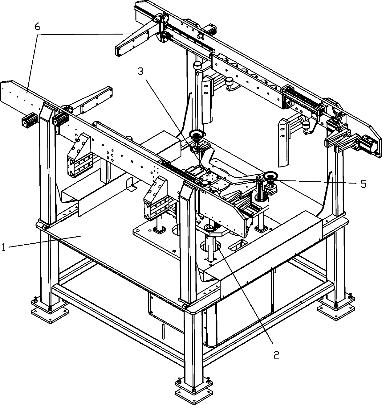
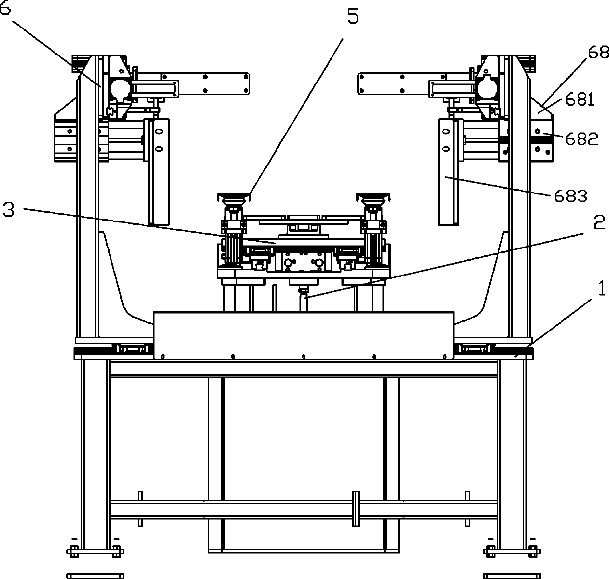
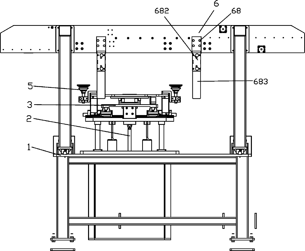
[0019] see Figure 1 to Figure 8 , a sunroof positioning station of the present invention, which includes,

[0020] A working platform 1 and its lower fixing bracket;

[0021] The lifting mechanism 2 is arranged in the center of the working platform 1, including:

[0022] The substrate 21 has guide holes 211 at its upper corners and a center hole 212 at the center, and the working platform 1 is provided with through holes corresponding to the guide holes 211 and the center hole 212;

[0023] The lifting platform 22 has guide pillars 23 at the four corners of the bottom surface, which are respectively inserted into the guide holes 211 at the four corners of the base plate 21;

[0024] The lifting cylinder 24 is vertically arranged under the working platform 1, and the end of the piston rod protrudes from the central hole 212 of the base plate 21 and is connected to the center of the bottom surface of the lifting platform 22;

[0025] X-Y adjustment assembly 3, including,

...


PUM


Abstract

The invention discloses a skylight positioning station which comprises a working platform, a lifting mechanism, an X-Y adjusting assembly, a rotating assembly, a taking assembly and a clamping mechanism. The lifting mechanism is arranged in the upper center of the working platform, the X-Y adjusting assembly is arranged on the lifting platform, the rotating assembly and the taking assembly are arranged on the X-Y adjusting assembly, the clamping mechanism is arranged on the working platform and comprises two moving guide rails, a sliding block, two moving assemblies, a first clamping assembly,a second clamping assembly, a third clamping assembly and two jacking assemblies, wherein the two moving guide rails are arranged on the two sides of the upper end face of the working platform in parallel, and the two moving assemblies are oppositely arranged on the two sides of the upper portion of the working platform and each comprise two moving supports, a driving air cylinder and an installation plate. The position of a skylight on the positioning station is accurate and unique, alignment for a mechanical hand is stable and reliable, automatic positioning for the skylight and taking positioning for the mechanical hand can be successfully completed, and high-quality products are provided for automatic plants.

Description

technical field [0001] The invention relates to the technical field of manipulators, in particular to a sunroof positioning station. Background technique [0002] The skylight positioning station is the transitional equipment between the skylight and the manipulator, and is the key equipment to realize the automatic material picking of the manipulator. [0003] The existing skylight positioning station cannot fundamentally solve the space positioning problem of the skylight, especially the problems such as correcting the position smoothly during the centering process and protecting the workpiece from damage. Contents of the invention [0004] The purpose of the present invention is to design a skylight positioning station, so that the location of the skylight at the positioning station can be accurate and unique, the centering of the manipulator is also stable and reliable, and the automatic positioning of the skylight and the material taking and positioning of the manipul...

Claims


Application Information

Patent Timeline
Patent Type & Authority Applications(China)
IPC IPC(8): B25J9/16
CPCB25J9/1669B25J9/1679
Inventor 李君成
Owner SHANGHAI TRANSCEND MACHINERY EQUIP CO LTD
Learn More