Eureka AIR delivers breakthrough ideas for toughest innovation challenges, trusted by R&D personnel around the world.

Tension control device suitable for light fabric

A tension control and fabric technology, used in transportation and packaging, strip winding, thin material handling, etc., to solve problems such as large tension changes and large sliding friction between rollers and warp yarns

Pending Publication Date: 2020-06-30
青岛天一红旗特种织机科技有限公司
View PDF0 Cites 1 Cited by
  • Summary
  • Abstract
  • Description
  • Claims
  • Application Information

AI Technical Summary

Problems solved by technology

In the prior art, there is no warp tension control device suitable for weaving low-tension variable fabrics under high-speed operation. The existing tension control structure is that the tension roller is supported on the lower transition roller mandrel, and the tension changes greatly during the weaving process. , the sliding friction between the roller and the warp is relatively large

Method used


Image

  • Tension control device suitable for light fabric
  • Tension control device suitable for light fabric
  • Tension control device suitable for light fabric

Examples


Embodiment 1

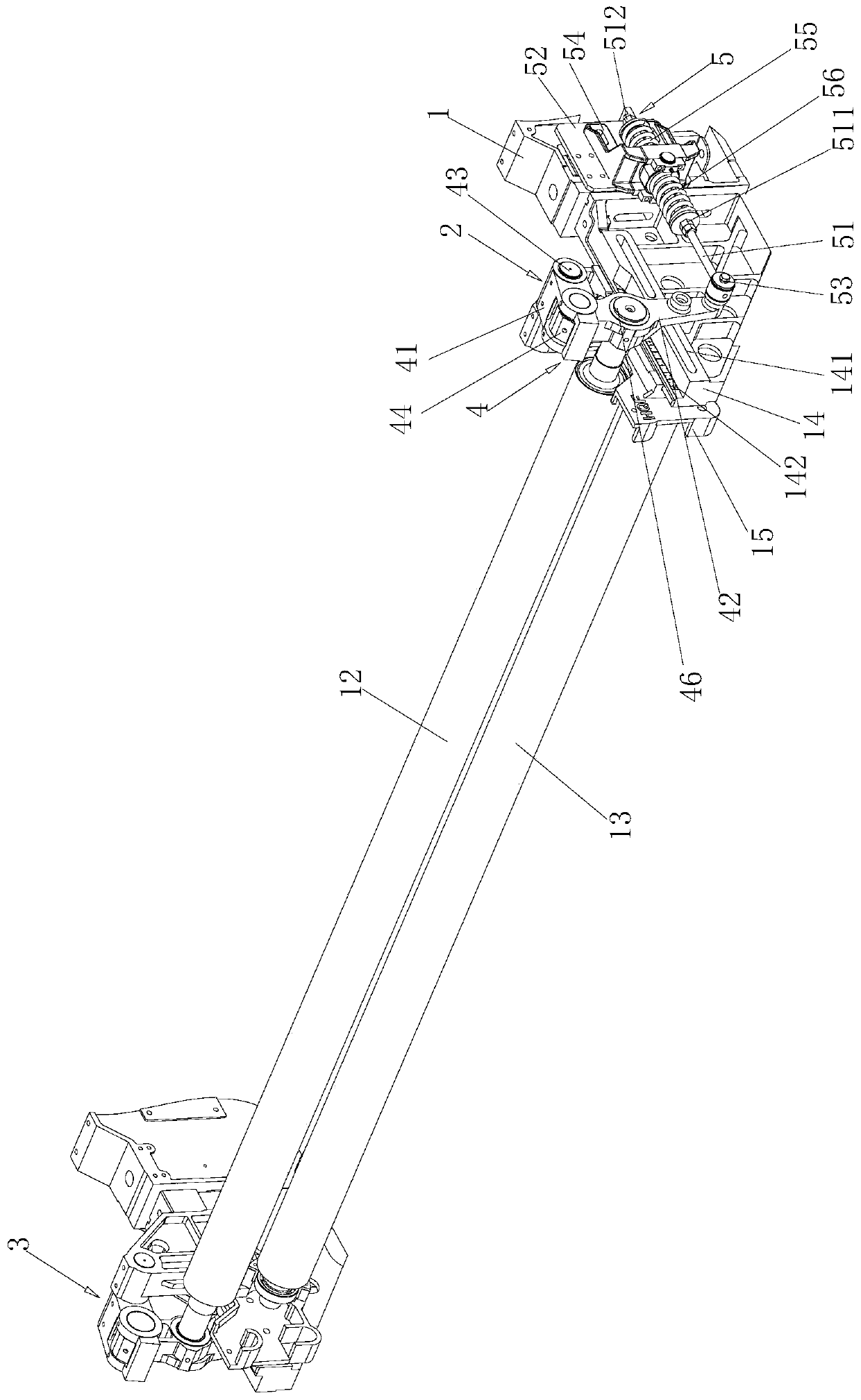
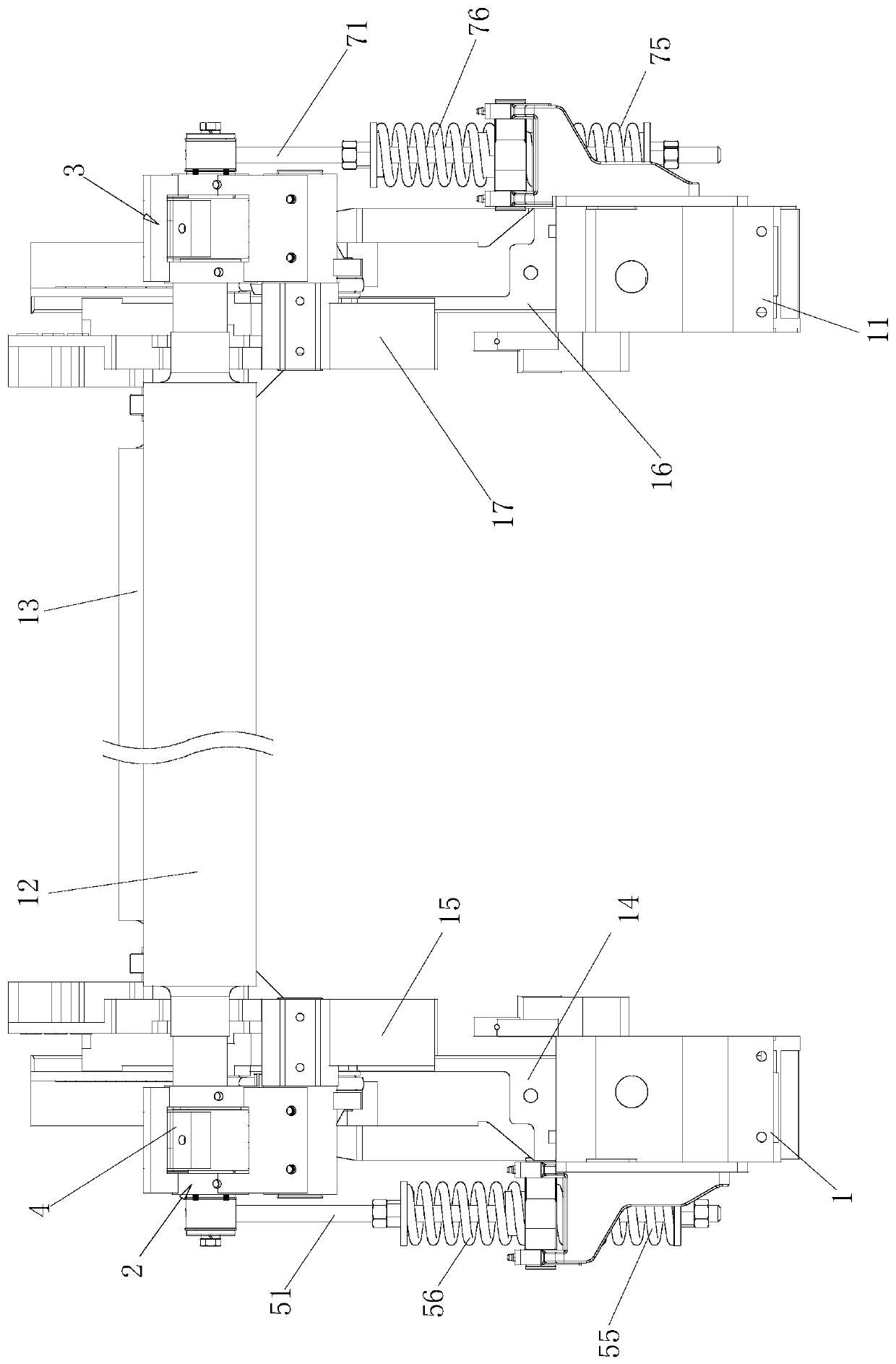
[0051] combine Figure 1 to Figure 7 , a tension control device suitable for light fabrics, including a left frame 1, a right frame 11, a tension roller 12 and a transition roller 13. The left frame 1 is connected with a left roller support 15 through a left elevating support 14 , and the right roller support 17 is connected with a right elevating support 16 on the right frame 11 .

[0052] The top of the left roller support 15 is connected with the left buffer linkage mechanism 2, the top of the left buffer linkage mechanism 2 is connected with the left end of the tension roller 12 in rotation, and the bottom of the left buffer linkage mechanism 2 is connected with the left frame 1 positioning.

[0053] The top of the right roller bracket 17 is connected with a right buffer linkage mechanism 3, the top of the right buffer linkage mechanism 3 is connected with the right end of the tension roller 12, and the bottom of the right buffer linkage mechanism 3 is positioned and conne...

Embodiment 2

[0078] combine Figure 1 to Figure 7 When the above-mentioned tension control device suitable for light fabrics is in operation, the warp yarn on the weaving beam 8 passes upward through the transition roller, then forward through the tension roller, and passes through the heald structure 81 to reach the weaving fell.

[0079] There are two states of warp passing:

[0080] The first type is the warp route in the heald state: the points A-B0-C0-D0-E0-F-G where the warp passes through;

[0081] The second type, the warp route in the opening state of the weaving fell:

[0082] The point through which the upper warp of this type passes is: A-B1-C1-D1-E1-F-G; the point through which the lower warp of this type passes is: A-B2-C2-D1-E1-F-G;

[0083] The warp yarn route lengths of the upper and lower layers are slightly different, and the tension of the upper and lower layers has little influence when the tension roller opens.

[0084] When the loom is opened and closed, the tensi...

Embodiment 3

[0088] combine Figure 1 to Figure 7 , in the above-mentioned tension control device suitable for light-duty fabrics, the tension roller is above the transition roller, leaning slightly forward (diagram Φ2), forming a larger wrap angle (diagram Φ1), so that the cloth fell A When switching between opening and closing, the tension roller only needs a small swing range to compensate for the warp variation between opening and closing. In this way, the tension roller follows the state better when running at high speed, and the tension change is relatively small.

[0089] The position of the fulcrum of the swing arm of the tension roller is slightly forward on the upper part of the roller, and the center of the fulcrum, the center of the tension roller, and the center of the transition roller are close to a straight line of 180°, so that when the tension roller swings, the tension roller The length of the rear warp rarely changes, because the tension roller does not rotate automatic...


PUM


Abstract

The invention discloses a tension control device suitable for light fabric. The device comprises a left rack, a right rack, a tension roller and a transition roller, wherein the left rack is connectedwith a left roller support through a left lifting support, the right rack is connected with a right roller support through a right lifting support, the upper portion of the left roller support is connected with a left buffering linkage mechanism, the upper portion of the left buffering linkage mechanism is rotationally connected with the left end of the tension roller, the lower portion of the left buffering linkage mechanism is in positioning connection with the left rack, the upper portion of the right roller support is connected with a right buffering linkage mechanism, the upper portion of the right buffering linkage mechanism is connected with the right end of the tension roller, the lower portion of the right buffering linkage mechanism is in positioning connection with the right rack, the transition roller is located below the tension roller, and the transition roller is connected between the lower portion of the left roller support and the lower portion of the right roller support through a bearing. The tension control device is more suitable for weaving small-tension variable fabrics in a high-speed running state, and is more novel in structure and higher in practicability.

Description

technical field [0001] The invention relates to the field of textile machinery, in particular to a tension control device suitable for light fabrics. Background technique [0002] The air-jet loom is a shuttleless loom that uses jet air to pull the weft through the shed. The working principle is to use the air as the weft insertion medium, and use the compressed air jet to generate friction and traction on the weft yarn to pull the weft yarn through the shed, and achieve the purpose of weft insertion through the jet generated by the air jet. In the process of weaving the warp yarn in the loom, the tension on the warp yarn is not constant. In the prior art, there is no warp tension control device suitable for weaving low-tension variable fabrics under high-speed operation. The existing tension control structure is that the tension roller is supported on the lower transition roller mandrel, and the tension changes greatly during the weaving process. , the sliding friction be...

Claims


Application Information

Patent Timeline
Patent Type & Authority Applications(China)
IPC IPC(8): B65H23/188B65H23/26B65H23/16
CPCB65H23/1888B65H23/26B65H23/16B65H2701/1133
Inventor 刘培德高玉刚孙士省朱靖宇吴海艳
Owner 青岛天一红旗特种织机科技有限公司
Why Eureka
Eureka Blog
Learn More