Surveying and mapping device
A surveying and mapping device and box technology, applied in the field of surveying and mapping tools, can solve the problems of damage to precision instruments inside the box, poor shock absorption effect, inconvenient tool access, etc., to improve the shock absorption effect, facilitate access, reduce The effect of dithering frequency
- Summary
- Abstract
- Description
- Claims
- Application Information
AI Technical Summary
Problems solved by technology
Method used
Image

Examples
Embodiment 1
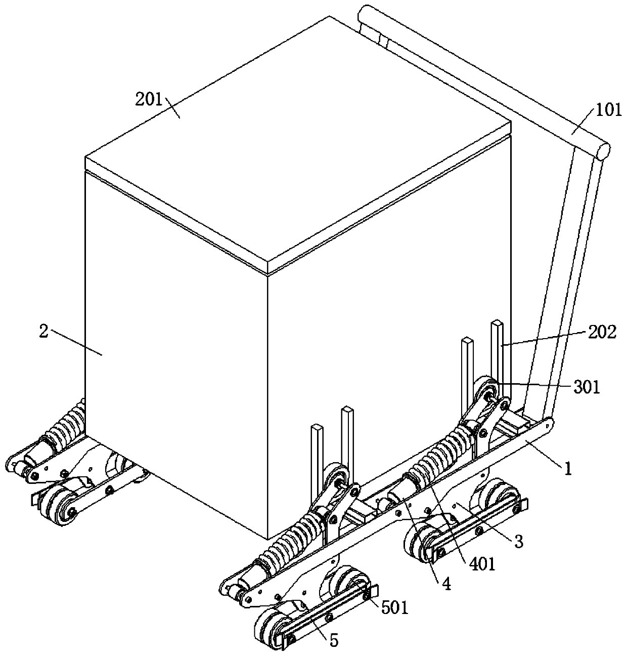
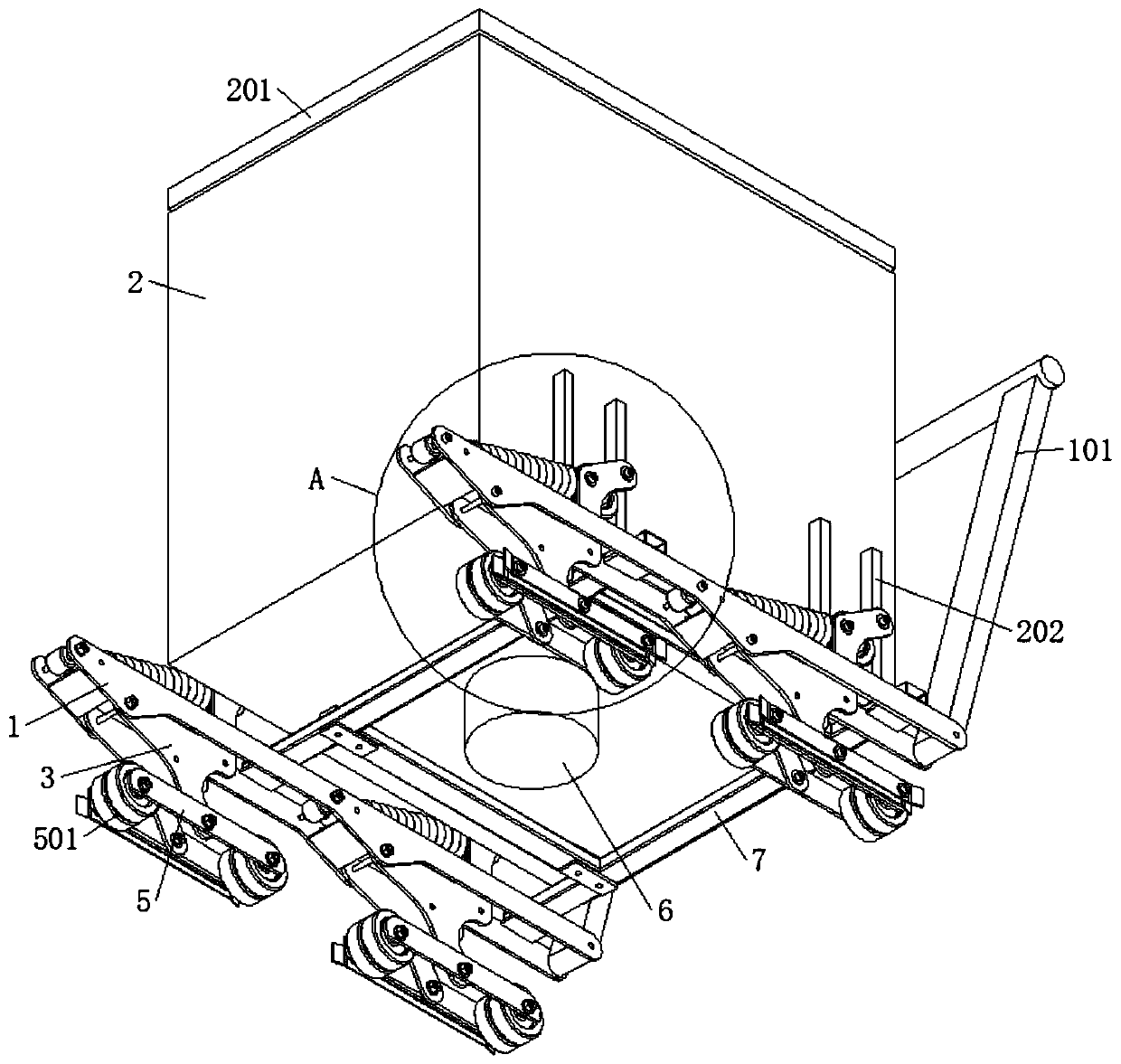
[0029] refer to Figure 1-7 , in order to improve the damping effect of existing surveying and mapping devices and to facilitate the taking of surveying and mapping tools, the application adopts the following technical means: it includes a base 1; a sliding frame 7 is used to slide and connect to the base 1; a box body 2, Used to be installed on the sliding frame 7; the tripod 3 is used to be connected to the base 1 and has three connection ends; wherein, one connection end of the tripod 3 is connected to the base 1 in rotation, and one connection end of the tripod 3 is connected to the base 1 The box body 2 is slidably connected, one end of the tripod 3 is rotatably connected to a splint 5, and the two ends of the splint 5 are rotatably connected to a wheel 501; an elastic component is used to connect between the base 1 and the tripod 3; a storage plate 603, It is slidably connected with the box body 2 and can move up and down relative to the box body 2; wherein, there are mu...
Embodiment 2
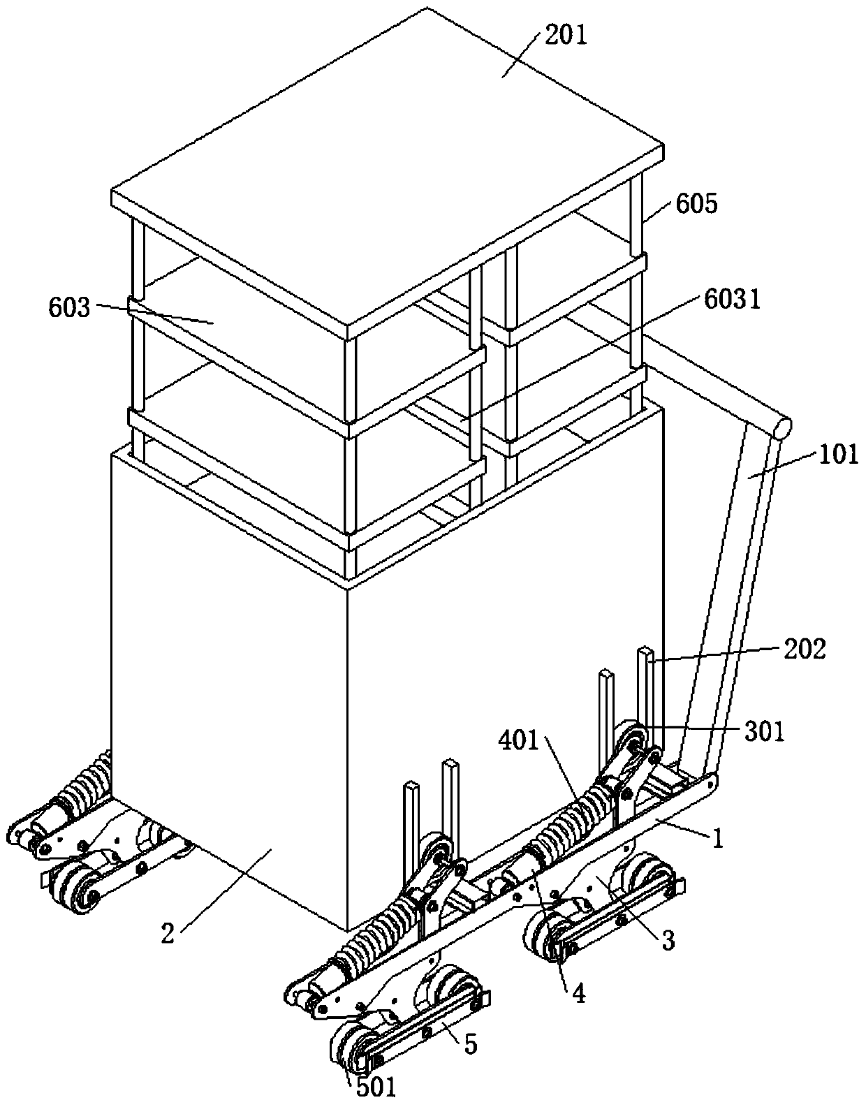
[0031] refer to image 3 , Figure 5 , which is basically the same as that of Embodiment 1, furthermore, this embodiment is a specific implementation of the drive assembly in Embodiment 1, which includes a motor 6 installed at the bottom of the box body 2, and a screw rod 601 is connected to the box body 2 for rotation , the output end of the motor 6 is connected with the screw rod 601, and a lifting plate 602 is slidably connected in the box body 2, and the lifting plate 602 is threadedly connected with the screw rod 601, and the top of the lifting plate 602 is fixedly connected with a plurality of storage plates 603 through a connecting rod 605. To drive the storage plate 603 up and down, the top of the box body 2 is provided with an opening, the storage plate 603 can move upwards through the opening at the top of the box body 2, and the motor 6 drives the screw rod 601 to rotate, so that the lifting plate 602 moves upwards, thereby passing The connecting rod 605 drives the...
Embodiment 3
[0036] refer to Figure 1-7 , is basically the same as Example 1, furthermore, this embodiment is a specific implementation of the drive assembly in Example 1, its elastic component includes a telescopic rod 4, and the telescopic rod 4 is sleeved to limit the contraction of the telescopic rod 4 One end of the telescopic rod 4 is rotatably connected to the base 1 , the other end is rotatably connected to the tripod 3 , and the connection point is close to the end that is slidably connected to the box body 2 .
[0037] The side wall of the box body 2 is fixedly connected with two symmetrical clamping strips 202, and the two clamping strips 202 form a clamping groove. One end of the tripod 3 is rotatably connected with a roller 301, and the roller 301 is rollingly connected in the clamping groove.
[0038] The base 1 is provided with a chute 102 , the sliding frame 7 is provided with a slider 701 , the slider 701 is slidably connected in the chute 102 , and the base 1 is fixedly ...
PUM
 Abstract
Description
Claims
Application Information
 - Generate Ideas
- Intellectual Property
- Life Sciences
- Materials
- Tech Scout
- Unparalleled Data Quality
- Higher Quality Content
- 60% Fewer Hallucinations
Browse by: Latest US Patents, China's latest patents, Technical Efficacy Thesaurus, Application Domain, Technology Topic, Popular Technical Reports.
© 2025 PatSnap. All rights reserved.Legal|Privacy policy|Modern Slavery Act Transparency Statement|Sitemap|About US| Contact US: help@patsnap.com