Tin printing coating iron drying room

A technology for printing iron coatings and drying rooms, applied in printing, printing machines, general parts of printing machinery, etc., can solve problems such as waste, heat loss, waste of resources, etc., and achieve the effects of reducing loss, slowing down heat loss, and reducing temperature difference

Inactive Publication Date: 2020-06-30
连云港富鑫包装有限公司
View PDF0 Cites 0 Cited by
  • Summary
  • Abstract
  • Description
  • Claims
  • Application Information

AI Technical Summary

Problems solved by technology

[0002] After the pattern is printed on the surface of the metal sheet, it needs to be dried to make the paint adhere closely. Generally, when drying in the drying room, it is heated by hot air circulation. On the one hand, the hot air discharged during the circulation process carries If the waste heat is discharged directly, it will be wasted. On the other hand, the heat exchange between the drying room and the external environment will lose a lot of heat, both of which are a waste of resources.

Method used


Image

  • Tin printing coating iron drying room
  • Tin printing coating iron drying room
  • Tin printing coating iron drying room

Examples


Embodiment Construction

[0018] The following will clearly and completely describe the technical solutions in the embodiments of the present invention with reference to the accompanying drawings in the embodiments of the present invention. Obviously, the described embodiments are only some, not all, embodiments of the present invention. Based on the embodiments of the present invention, all other embodiments obtained by persons of ordinary skill in the art without making creative efforts belong to the protection scope of the present invention.

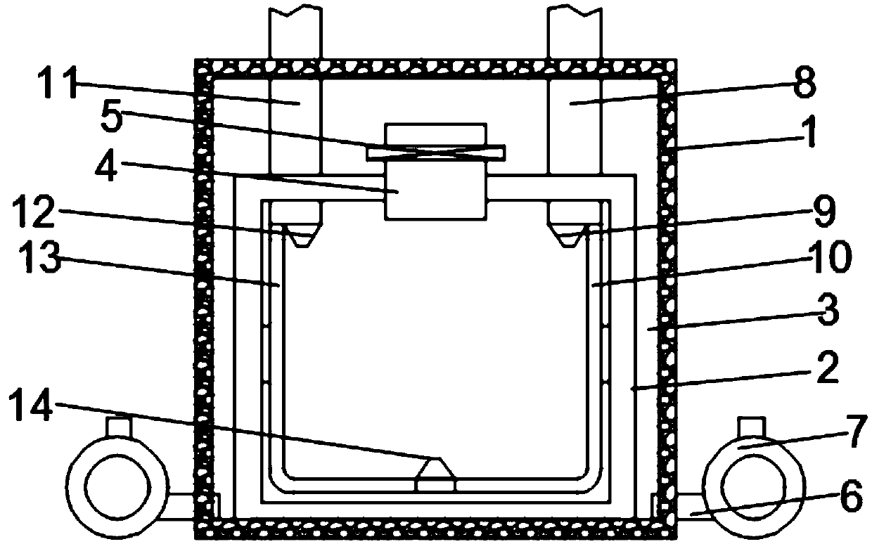
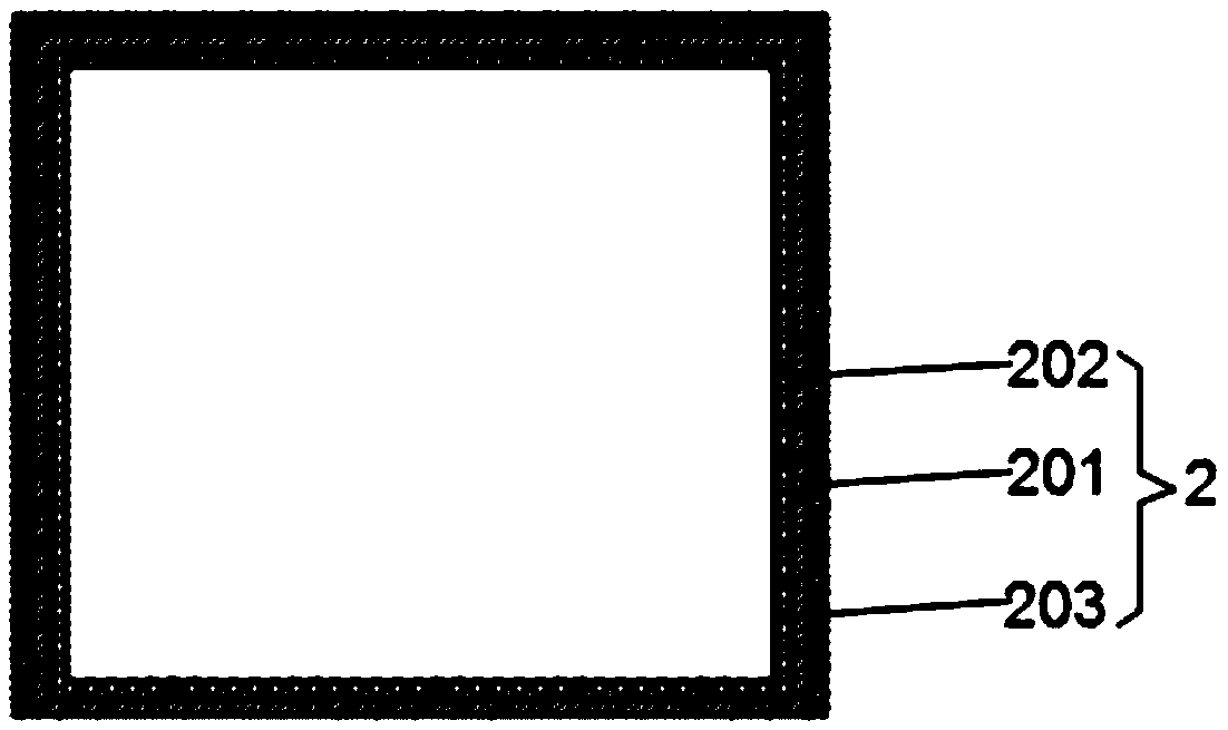
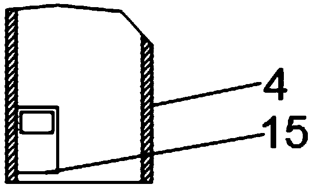
[0019] see Figure 1-3 , the present invention provides a technical solution: an iron printing and coating iron drying room, including a drying room body 1, a drying room body 2 is fixedly connected to the bottom of the inner wall of the drying room body 1, and the outer wall of the drying room body 2 is connected to the drying room body 1 A waste heat utilization chamber 3 is formed between the inner walls, and an air pipe 4 is fixedly connected to the middle...


PUM


Abstract

The invention discloses a tin printing coating iron drying room. The tin printing coating iron drying room comprises a drying room body, wherein the bottom of the inner wall of the drying room body isfixedly connected with a drying room body; a waste heat utilization cavity is formed between the outer wall of the drying room body and the inner wall of the drying room body; the middle position ofthe top of the drying room body fixedly communicates with a gas conveying pipe; one end of the gas conveying pipe communicates with the waste heat utilization cavity; an electromagnetic valve is arranged in the middle of the gas conveying pipe; the lower ends of the two sides of the outer wall of the drying room body fixedly communicate with exhaust pipes; the ends, away from the drying room body,of the exhaust pipes fixedly communicate with exhaust fans; one side of the top of the drying room body fixedly communicates with a first hot air pipe; and one end of the first hot air pipe extends into the drying room body. The invention relates to the technical field of drying rooms. The tin printing coating iron drying room achieves the purpose of secondary utilization of waste heat, reduces the loss of resources, increases the speed of increasing the temperature in the drying room, and reduces the loss of heat.

Description

technical field [0001] The invention relates to the technical field of drying rooms, in particular to an iron printing and coating iron drying room. Background technique [0002] After the pattern is printed on the surface of the metal sheet, it needs to be dried to make the paint adhere closely. Generally, when drying in the drying room, it is heated by hot air circulation. On the one hand, the hot air discharged during the circulation process carries If the waste heat is discharged directly, it will be wasted. On the other hand, the heat exchange between the drying room and the external environment will cause a large amount of heat loss. Both of these are a waste of resources. Contents of the invention [0003] (1) Solved technical problems [0004] Aiming at the deficiencies of the prior art, the invention provides an iron printing and coating iron drying room, and provides an iron printing and coating iron drying room for secondary utilization of waste heat. [0005]...

Claims


Application Information

Patent Timeline
IPC IPC(8): B41F23/04
CPCB41F23/04
Inventor 邵世志
Owner 连云港富鑫包装有限公司
Why Eureka
Try Eureka