Wireless detection method suitable for mast photoelectric reconnaissance equipment

A wireless detection and photoelectric reconnaissance technology, applied in wireless communication, electrical components, safety devices, etc., can solve the problems of personal safety hazards, the lifting process should not be too fast, and affect the long-distance detection and tracking accuracy of equipment, etc., to achieve simple composition, Avoid working steps, real-time over-the-air debugging and detection effects

Active Publication Date: 2020-06-26
西安应用光学研究所
View PDF4 Cites 0 Cited by
  • Summary
  • Abstract
  • Description
  • Claims
  • Application Information

AI Technical Summary

Problems solved by technology

First of all, the mast photoelectric reconnaissance equipment is generally installed in a position that is not easy or inaccessible to people. If the mast cannot be raised or retracted, there will be certain personal safety hazards during debugging and troubleshooting
Secondly, for the retractable mast photoelectric reconnaissance equipment, professionals are required to operate the lifting and lowering process during debugging or fault detection, which increases the cost of debugging and fault detection personnel
For the sake of equipment safety, the lifting process should not be too fast, which also seriously affects the timeliness of debugging, especially fault detection.
Third, the change of mast height will inevitably cause random error changes in the system when the retractable mast photoelectric reconnaissance equipment is raised and lowered, which will affect the long-distance detection and tracking accuracy of the equipment
Fourth, after the lifting and shrinking of the mast photoelectric reconnaissance equipment, the system must check the horizontal consistency of the mast bearing platform again, and the parameters of the photoelectric system, such as azimuth and pitch zero, must also be rechecked and bound, which improves the debugging process. or the complexity of fault detection

Method used


Image

  • Wireless detection method suitable for mast photoelectric reconnaissance equipment
  • Wireless detection method suitable for mast photoelectric reconnaissance equipment
  • Wireless detection method suitable for mast photoelectric reconnaissance equipment

Examples


Embodiment Construction

[0033] In order to make the purpose, content, and advantages of the present invention clearer, the specific implementation manners of the present invention will be further described in detail below in conjunction with the accompanying drawings and embodiments.

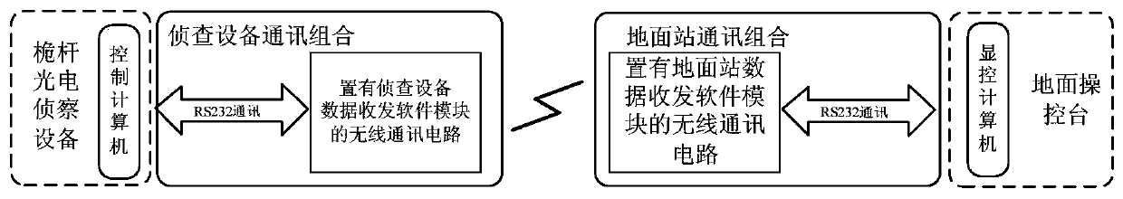
[0034] In order to solve the problems in the prior art, the present invention provides a wireless detection method suitable for mast photoelectric reconnaissance equipment. The wireless detection method is implemented based on a wireless detection system, and the wireless detection system includes: a reconnaissance equipment communication combination and a ground station communication combination; the reconnaissance equipment communication combination includes a reconnaissance equipment data transceiver module and a second asynchronous serial communication circuit; the ground station communication combination includes a ground station data transceiver module and a first asynchronous serial communication circuit;

[0035...


PUM


Abstract

The invention belongs to the technical field of photoelectric detection, and particularly relates to a wireless detection method suitable for mast photoelectric reconnaissance equipment, in particularto debugging and fault detection suitable for elevated, high-maneuverability and telescopic mast photoelectric reconnaissance equipment. In the present invention, the ground station communication combination communicates with a display control computer of a ground console through a serial port; the upper computer communication combination communicates with the control computer of the mast photoelectric reconnaissance equipment through a serial port, a wireless network is established between the two communication combinations, and wireless communication between the display control computer ofthe ground console and the control computer of the mast photoelectric reconnaissance equipment is achieved. By means of the wireless communication mode, the ground console can achieve non-contact, uninterrupted power and real-time wireless debugging and detection of mast photoelectric reconnaissance equipment.

Description

technical field [0001] The invention belongs to the technical field of photoelectric detection, and in particular relates to a wireless detection method suitable for mast photoelectric reconnaissance equipment, in particular to debugging and fault detection suitable for elevated, high maneuverability, liftable mast photoelectric reconnaissance equipment. Background technique [0002] Mast photoelectric reconnaissance equipment is a photoelectric search and tracking system that integrates multiple sensors such as visible light, infrared, and laser, and is used to detect and track low-altitude and sea-surface targets. It has all-weather reconnaissance targets and the ability to provide real-time target indication. Compared with radar, mast photoelectric reconnaissance equipment has good concealment and strong anti-electromagnetic interference ability, especially for stealth aircraft, and its advantages cannot be compared with other equipment. At present, various arms of the mi...

Claims


Application Information

Patent Timeline
Patent Type & Authority Applications(China)
IPC IPC(8): H04W24/00H04W12/06H04W48/16
CPCH04W24/00H04W48/16H04W12/72H04W12/068Y02D30/70
Inventor 吴青靑王新明王璞成莉王敏王明歆王佳姚林海刘彤赵磊王权幕巍
Owner 西安应用光学研究所
Why Eureka
Try Eureka