


Quick Research
Generate reliable direction feasibility study reports for your R&D in just a few steps.

Technical Q&A
Discover and master advanced knowledge NOW. Basics, ideas, possibilities, all at once.

Find Solutions
As an expert in R&D theories, this can generate solutions to your technical problems instantly.

Evaluate Feasibility
Analyze your overall solution with one click, know your potential R&D risks in advance.

Monitor Landscape
Get weekly tech updates, stay abreast of the latest tech innovations and key insights.
Optical system of annular light spot
An optical system and ring-shaped spot technology, which is applied in optics, optical components, laser welding equipment, etc., can solve the problems of low conversion efficiency and damage of ring-shaped beams, and achieve the effect of not easy to diffract, high energy conversion rate, and easy to realize
- Summary
- Abstract
- Description
- Claims
- Application Information
AI Technical Summary
Problems solved by technology
Method used
Image

Examples
Embodiment 1
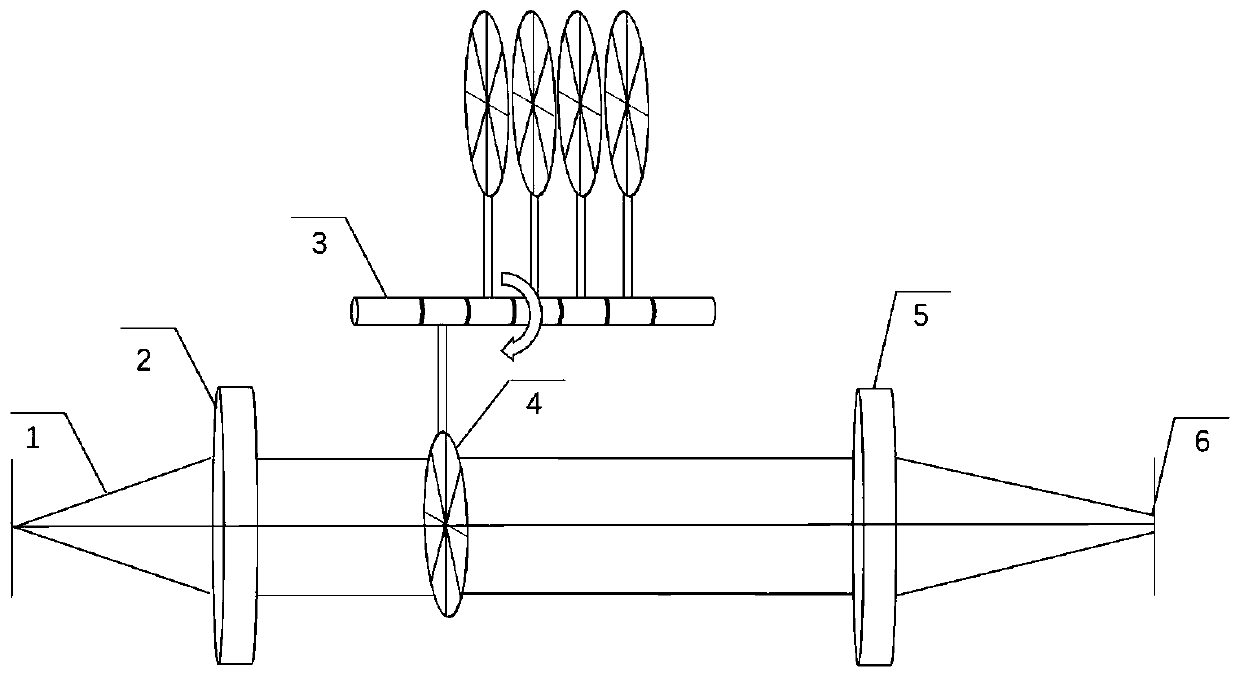
[0046] The schematic diagram of the variable annular spot optical system provided by the first embodiment of the present invention is as follows figure 1 As shown, the whole system is divided into collimation unit, phase modulation unit and focusing unit. The laser beam is collimated into parallel light through the lens group of the collimation unit, and then enters from the plane end of the helical phase plate in the phase modulation unit, and emerges as a ring beam, whose topological charge is equal to that of the helical phase plate. Finally, the light spot with annular energy distribution is obtained by focusing through the lens group in the focusing unit.
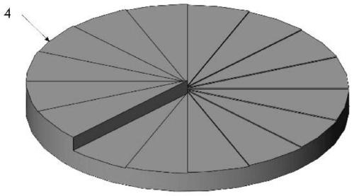
[0047] like figure 2 Shown is a schematic structural diagram of the spiral phase plate in the variable annular spot optical system of the present invention. The spiral phase plate is an optical element in the prior art. In the prior art, the spiral phase plate is made into steps for the convenience of processing sha...
Embodiment 2
[0057] The schematic diagram of the variable annular spot system provided by the second embodiment of the present invention is as follows Figure 10 As shown, the laser beam passes through the collimation unit and the phase modulation unit, then passes through two scanning galvanometers, and finally passes through the focusing objective lens. mark.
[0058] The optical path of embodiment 2 and the energy distribution of the light field on the focusing plane are consistent with those of embodiment 1. Since the annular light spot produced by the spiral phase plate has high stability, the characteristics of annular distribution can still be maintained at the position away from the focal point. During the high-speed moving marking process of the galvanometer scanning, the circular energy output can be well maintained. Compared with the application of the embodiment 1 in the vertical space, the application of the embodiment 2 is mainly in the horizontal space.
[0059] In general,...
PUM
| Property | Measurement | Unit |
|---|---|---|
| Radius | aaaaa | aaaaa |
Abstract
Description
Claims
Application Information
 - R&D Engineer
- R&D Manager
- IP Professional
- Industry Leading Data Capabilities
- Powerful AI technology
- Patent DNA Extraction
Browse by: Latest US Patents, China's latest patents, Technical Efficacy Thesaurus, Application Domain, Technology Topic, Popular Technical Reports.
© 2024 PatSnap. All rights reserved.Legal|Privacy policy|Modern Slavery Act Transparency Statement|Sitemap|About US| Contact US: help@patsnap.com