
Low Frequency Inductive Magnetic Sensor Based on Nonvolatile Tuning

A magnetic sensor and inductive technology, used in instruments, measuring magnetic variables, measuring devices, etc., can solve the problems of magnetic loss of soft magnetic materials, increase the cost of current sources, limit wide application, etc., to achieve non-volatile tuning, improve Effective magnetic permeability, the effect of enhancing the convergence ability

Active Publication Date: 2020-11-10
SHANGHAI JIAO TONG UNIV
View PDF5 Cites 0 Cited by
  • Summary
  • Abstract
  • Description
  • Claims
  • Application Information

AI Technical Summary

Problems solved by technology

However, the current GMI thin-film magnetic sensors have the following problems: first, most soft magnetic thin films need to apply a very high-frequency (MHz or even GHz) AC excitation current to obtain the maximum GMI effect due to the weak low-frequency skin effect, which is harmful to the soft magnetic sensor. The magnetic material causes severe magnetic loss and significantly increases the cost of the current source, thus limiting the wide application of GMI thin-film magnetic sensors
However, it still has the low magnetic permeability of the soft magnetic film and the complex structure of the laminated coil. In the sensing process, only relying on the measured magnetic field to adjust the magnetic permeability of the soft magnetic film causes the output voltage of the magnetic sensor to change, making the final resolution of the magnetic sensor Severely limited by defects such as the maximum magnetic permeability of the material

Method used


Image

  • Low Frequency Inductive Magnetic Sensor Based on Nonvolatile Tuning
  • Low Frequency Inductive Magnetic Sensor Based on Nonvolatile Tuning
  • Low Frequency Inductive Magnetic Sensor Based on Nonvolatile Tuning

Examples


Embodiment Construction

[0020] The present invention will be further described below in conjunction with the accompanying drawings and examples, but the protection scope of the present invention should not be limited thereto.

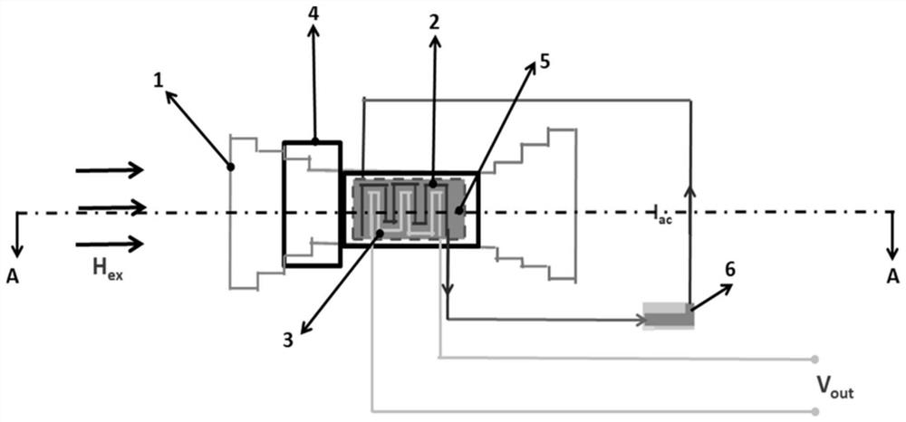
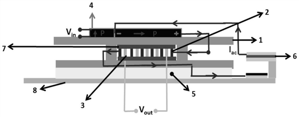
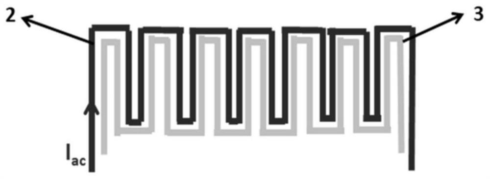
[0021] according to figure 1 with figure 2 , as can be seen from the figure, the present invention is based on a non-volatile tuned low-frequency inductive magnetic sensor, including a sensing unit structure and an adjustable capacitance 6 driven by a piezoelectric beam, and the sensing unit structure is on the substrate 8 From bottom to top, giant magnetostrictive layer 5, multi-layer stepped soft magnetic film 1, insulating layer 7, integrated planar excitation coil 2 and planar induction coil 3, insulating layer 7, multi-layer stepped soft magnetic film 1 , piezoelectric transformer layer 4; the integrated planar excitation coil 2 and planar induction coil 3, insulating layer 7, and multi-layer stepped soft magnetic film 1 form a sandwich structure, and the adjustable cap...


PUM


Abstract

The invention discloses a low-frequency induction type magnetic sensor based on non-volatile detuning. The sensor comprises a sensing unit structure and an adjustable capacitor driven by a piezoelectric beam, and the sensing unit structure comprises a giant magnetostrictive layer, a multi-layer stepped soft magnetic film, an insulating layer, an integrated planar excitation coil, a planar induction coil, an insulating layer, a multi-layer stepped soft magnetic film and a piezoelectric transformer layer which are sequentially arranged on a substrate from bottom to top; the effective magnetic conductivity of the soft magnetic thin film is improved. Meanwhile, the excitation current frequency is reduced, the AC driving capacity of the soft magnetic thin film is enhanced through boosting voltage and synchronous electrostriction stress obtained through the piezoelectric transformer layer, and the power consumption of a device is reduced. Meanwhile, magnetic domain movement is accelerated through magnetic force generated by the giant magnetostrictive material, so that the bottleneck of the maximum magnetic conductivity of the material is broken through, and the sensitivity is further improved. Finally, a new thought and a new method are provided for realizing a passive wireless ultrahigh-resolution and low-power-consumption magnetic sensing system in combination with an electromechanical resonance mechanism of non-volatile detuning.

Description

technical field [0001] The invention relates to a DC and low-frequency magnetic field sensor, in particular to a low-frequency inductive magnetic sensor based on non-volatile tuning. Background technique [0002] Weak magnetic field measurement technology has been widely used in geomagnetic-assisted navigation systems, biomagnetic field detection, military target detection, smart grid monitoring and other fields. For example, the magnetic field generated by biological systems (such as the human heart) is extremely weak (10pT ~ 100pT) and the frequency is low (0.1Hz-100Hz), which means that it is urgent to study ultra-high resolution (pT level) magnetic field sensors to achieve accurate detection function. At present, superconducting quantum interferometer (hereinafter referred to as SQUID) is mainly used for weak magnetic field detection of pT level (such as human heart magnetic detection), and its resolution limit can reach 10 -15 T. But SQUID must work below the tempera...

Claims


Application Information

Patent Timeline
Patent Type & Authority Patents(China)
IPC IPC(8): G01R33/07
CPCG01R33/072
Inventor 王遥文玉梅李平陈蕾
Owner SHANGHAI JIAO TONG UNIV
Learn More