A hydraulic start-stop device

A hydraulic and hydraulic pump technology, applied in the field of hydraulic start-stop devices, can solve the problems of engine fuel consumption and emission noise.

Active Publication Date: 2021-03-09
HUNAN MECHANICAL & ELECTRICAL POLYTECHNIC
View PDF5 Cites 0 Cited by
  • Summary
  • Abstract
  • Description
  • Claims
  • Application Information

AI Technical Summary

Problems solved by technology

[0006] The invention provides a hydraulic start-stop device, aiming to solve the technical problems of fuel consumption, emission and noise in the engine of the existing working machinery at idle speed

Method used


Image

  • A hydraulic start-stop device
  • A hydraulic start-stop device
  • A hydraulic start-stop device

Examples


Embodiment Construction

[0058] In order to better understand the above-mentioned technical solution, the above-mentioned technical solution will be described in detail below in conjunction with the accompanying drawings and specific implementation methods.

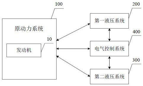
[0059] Such as figure 1 As shown, the first embodiment of the present invention proposes a hydraulic start-stop device, including a prime mover system 100, a first hydraulic system 200, a second hydraulic system 300 and an electrical control system 400, wherein the prime mover system 100 includes an engine 10 for providing Energy; the first hydraulic system 200 is connected with the prime mover system 100, and is used to transmit and convert the energy provided by the prime mover system 100, and to perform work and output energy to complete the expected action or function of the equipment; the second hydraulic system 300 and the prime mover system 100 It is used to absorb and store the energy of the prime mover system 100, and assist the drive of...


PUM


Abstract

The invention discloses a hydraulic start-stop device, comprising a prime mover system, a first hydraulic system, a second hydraulic system and an electrical control system, the prime mover system includes an engine, and is used to provide energy; the first hydraulic system is used to provide power to the prime mover system The energy is transferred and converted, and the energy is output by external work to complete the expected action or function of the equipment; the second hydraulic system is used to absorb and store the energy of the prime mover system, and assist the drive of the prime mover system through the stored energy; the electrical control system is used to detect The state parameters of the prime mover system, the first hydraulic system, and the second hydraulic system; if the working device driven by the first hydraulic system and the second hydraulic system does not move, and no operation command is received, the engine is shut down. The hydraulic start-stop device provided by the invention has few additional components and occupies a small space; it can reduce the model selection specification of the engine, reduce the total cost of the working machine, and reduce the fuel consumption, emission and noise of the prime mover.

Description

technical field [0001] The invention relates to the field of power system control, and in particular discloses a hydraulic start-stop device. Background technique [0002] Operating machinery includes engineering machinery, agricultural machinery, mining machinery, sanitation machinery, engineering vehicles, industrial equipment, etc. Among them, the power system of the working machine is divided into two categories: one is to use the energy provided by the environment, such as the use of mains power; the other is to use the prime mover carried by the working machine itself, such as internal combustion engine, electric motor and other prime movers. [0003] For working machines with self-contained internal combustion engines, in the process of design and use, there will generally be energy consumption problems of internal combustion engines, especially energy consumption problems under low power output conditions. [0004] In the prior art, the energy consumption of the int...

Claims


Application Information

Patent Timeline
Patent Type & Authority Patents(China)
IPC IPC(8): F15B1/02F15B21/08F15B19/00F02N19/00
CPCF02N19/00F15B1/02F15B19/00F15B21/005F15B21/087F15B2211/212
Inventor 韩慧仙陶东波舒常平
Owner HUNAN MECHANICAL & ELECTRICAL POLYTECHNIC
Why Eureka
Try Eureka