A Rapidly Prototyped Lap Joint Structure of Prefabricated Reinforcement Skeleton

A steel frame and joint structure technology, applied in structural elements, building components, building structures, etc., can solve the problems of long steel bar length, uneven steel bar binding and fixing, and inability to adjust the size of the steel cage frame, etc., to achieve the adjustment of side length, Convenient and fast binding effect

Active Publication Date: 2021-11-09
东至县尧春富农家庭农场
View PDF0 Cites 0 Cited by
  • Summary
  • Abstract
  • Description
  • Claims
  • Application Information

AI Technical Summary

Problems solved by technology

[0006] The purpose of the present invention is to provide a kind of assembly-type steel bar frame rapid prototyping lap joint structure, to solve the existing steel bar frame on the market that the above-mentioned background technology proposes, when binding, due to adopting the mode of binding wire and stirrups to the steel bar Bundle and fix. In this way, when binding the steel bars, the steel bars need to be bound at the four corners of the stirrups. Due to the long length and heavy weight of the steel bars, it is not convenient for construction workers to bind and fix the steel bars well. , when lapping the reinforcement cage skeleton, since different sizes of concrete wall columns or walls need to use different sizes of stirrups, the existing stirrups are generally in the form of fixed iron rings, which have poor versatility and cannot be used for reinforcement cages. The problem of adjusting the skeleton size

Method used


Image

  • A Rapidly Prototyped Lap Joint Structure of Prefabricated Reinforcement Skeleton
  • A Rapidly Prototyped Lap Joint Structure of Prefabricated Reinforcement Skeleton
  • A Rapidly Prototyped Lap Joint Structure of Prefabricated Reinforcement Skeleton

Examples


Embodiment Construction

[0033] Based on the embodiments of the present invention, all other embodiments obtained by persons of ordinary skill in the art without making creative efforts belong to the protection scope of the present invention.

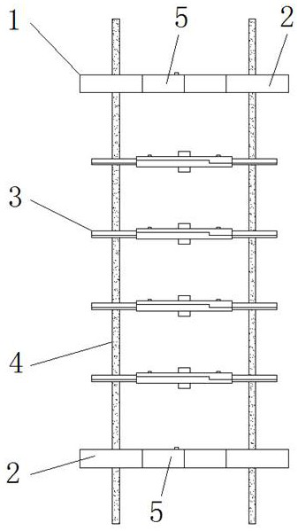
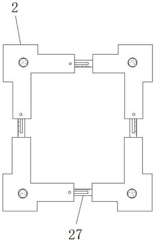
[0034] see Figure 1-11, the present invention provides a technical solution: an assembled steel bar skeleton rapid prototyping lap joint structure, including a lap joint structure body 1, an outer lap joint plate 2, a middle lap joint frame 3, steel bars 4, slots 5, and inner cavity holes 6. Limit hole 7, top tight block 8, limit chute 9, spring 10, top tight mouth 11, first support frame 12, second support frame 13, rotating shaft 14, connection groove 15, first adjustment groove 16. First adjusting frame 17, locking knob 18, rotating groove 19, clamping block 23, rotating shaft 21, top tightening groove 22, clamping port 20, pushing part 24, clamping part 25, second adjusting groove 26 With the second adjustment frame 27, the upper and lower ends of the lap...


PUM


Abstract

The invention discloses an assembled steel bar skeleton rapid forming lap joint structure, which comprises a lap joint structure body, an outer lap joint plate, a middle lap joint frame, steel bars, a rotating shaft and a locking knob. The upper and lower parts of the lap joint structure body Both ends are provided with external lapping plates, and middle lapping frames are equidistantly distributed between the two external lapping plates, and steel bars are interspersed on the external lapping plates and the middle lapping frames, and the first adjusting groove A first adjustment frame is interspersed inside, and the upper end surface of the first adjustment frame is provided with a top tight groove, the upper ends of the first support frame and the second support frame are threaded with locking knobs, and the inner ends of the locking knobs Connected with top tight groove. According to the overlapping characteristics of the steel cage skeleton, the fast forming lap joint structure of the prefabricated steel bar skeleton is designed to fix the steel bar, which can realize the fast fixing of the steel bar, and can adjust the binding size of the steel cage skeleton, which is convenient for construction workers. Fast lashing of reinforcement cages.

Description

technical field [0001] The invention relates to the technical field of prefabricated buildings, in particular to a rapid prototyping lap joint structure of prefabricated steel bar skeletons. Background technique [0002] Reinforced skeleton is a reinforced skeleton inside the concrete commonly used in the construction industry. It can install a corresponding length of reinforced skeleton at the place where the concrete needs to be poured before pouring concrete, and set up a peripheral formwork on the periphery of the reinforced skeleton, and finally , add the mixed concrete into the peripheral formwork, and after the concrete is solidified, remove the peripheral formwork. The steel skeleton can improve the strength of the concrete pillar or wall, increase the tensile strength of the concrete pillar or wall, and increase the overall strength of the building. construction strength. [0003] When bundling the overlapping reinforcement skeleton, it is generally to use square o...

Claims


Application Information

Patent Timeline
Patent Type & Authority Patents(China)
IPC IPC(8): E04C5/06E04G21/12
CPCE04C5/06E04C5/0627E04G21/123
Inventor 陈庆发
Owner 东至县尧春富农家庭农场
Why Eureka
Try Eureka