
Adjusting device for upper knife holder and upper circular knife of upper knife shaft of splitting machine, and preparation method

A technology of slitting machine and tool holder, which is applied in metal processing and other directions, can solve the problems of easy loosening, low fit, and increase the diversity of upper tool holder parts, so as to improve the cutting accuracy, improve the tightening relationship, and improve the The effect of slitting efficiency

Pending Publication Date: 2020-06-26
苏州市乾丰造纸机械制造有限公司
View PDF0 Cites 2 Cited by
  • Summary
  • Abstract
  • Description
  • Claims
  • Application Information

AI Technical Summary

Problems solved by technology

The existing upper tool holder is sleeved on the upper tool shaft. Generally, the upper tool holder is fastened to the upper tool shaft through a fixed block. The fixed block has the following defects: First, the degree of cooperation between the fixed block and the upper tool shaft is relatively low. Low, it is easy to loosen during the operation of the upper tool shaft, resulting in poor fixing effect of the fixing method, and frequent inspection and maintenance are required; the second is the above-mentioned fixing method, it is necessary to set at least 2 on the upper tool holder for accommodating the fixing block. The groove increases the processing procedure of the upper tool holder, which makes the processing procedure of the upper tool holder more complicated; the third is that the fixed block is fixed, and the fixed block is used as a separate part, which increases the diversity of parts of the upper tool holder, resulting in relatively low installation efficiency. Low, parts are not easy to store

Method used


Image

  • Adjusting device for upper knife holder and upper circular knife of upper knife shaft of splitting machine, and preparation method
  • Adjusting device for upper knife holder and upper circular knife of upper knife shaft of splitting machine, and preparation method
  • Adjusting device for upper knife holder and upper circular knife of upper knife shaft of splitting machine, and preparation method

Examples


Embodiment

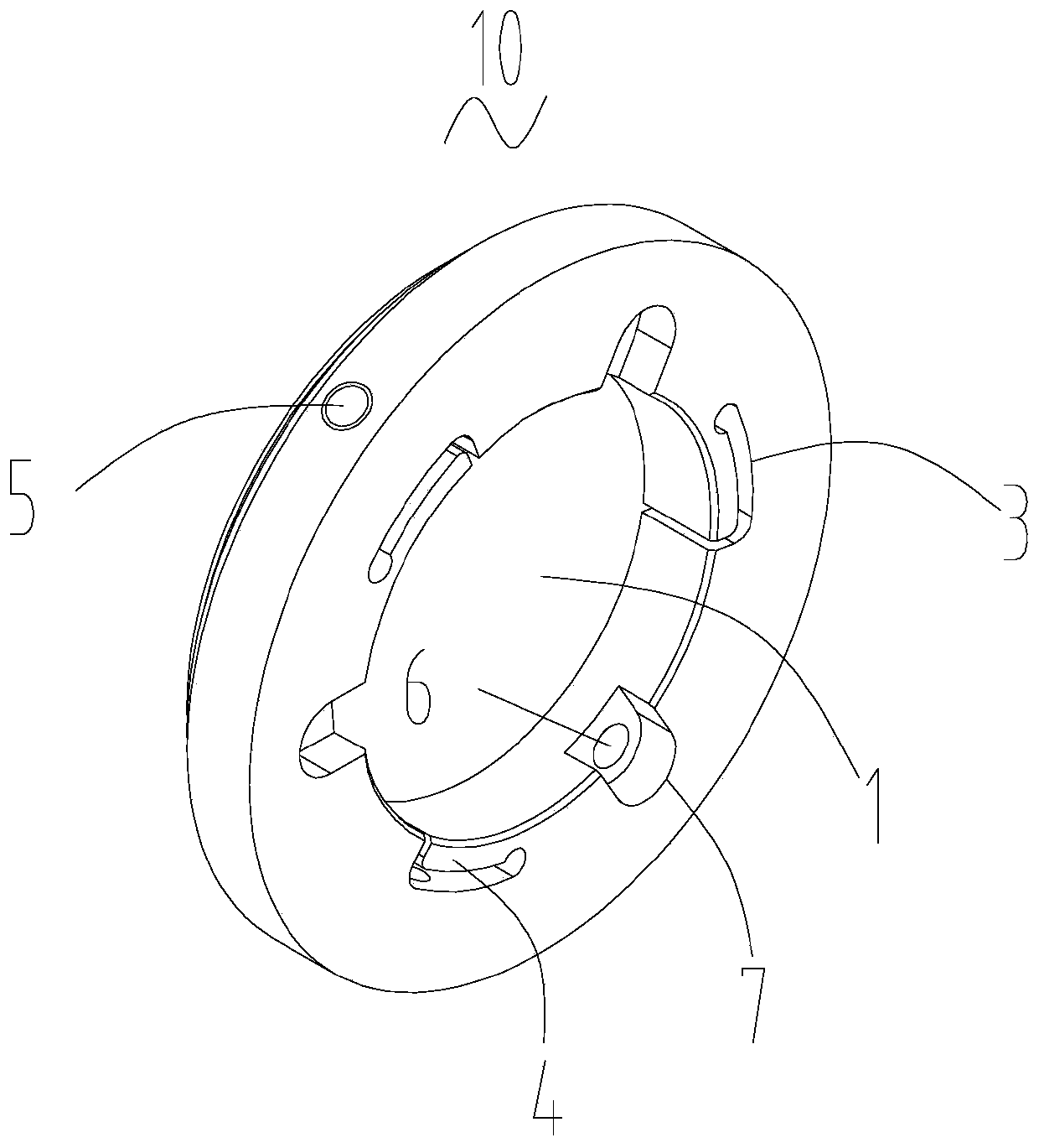
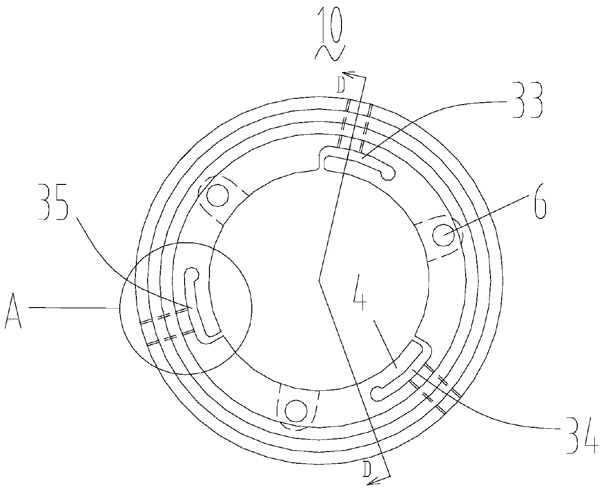
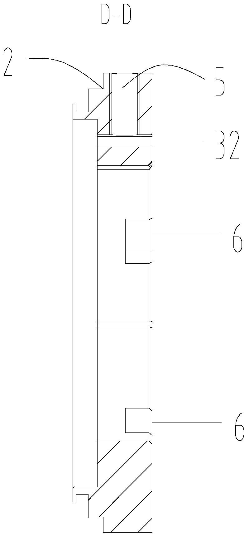
[0032] Such as Figure 1-7 As shown, the present invention provides an upper knife holder 10 of the upper knife shaft of the slitting machine, which includes a round hole 1 matched with the upper knife shaft and a card slot 2 for engaging the upper round knife. The upper knife holder 10 is close to At least one locking slit 3 is provided in the side area of ​​the upper knife shaft. By setting the locking slit, a locking block that is integrally formed with the upper knife holder 10 and perfectly matched with the upper knife shaft is formed on the upper knife holder 10. 4. Instead of the existing separately set fixed block, on the one hand, the degree of cooperation between the upper tool holder 10 and the upper tool shaft is greatly improved, thereby effectively improving the locking degree and firmness of the upper tool holder 10 and the upper tool shaft; on the other hand On the one hand, the processing steps of the upper tool holder 10 are effectively reduced, and the proce...


PUM


Abstract

The invention discloses an adjusting device for an upper knife holder and an upper circular knife of an upper knife shaft of a splitting machine, and preparation method, and relates to the technical field of a splitting machine. The adjusting device includes a round hole matched with the upper knife shaft and a clamping slot used for clamping the upper circular knife. At least one locking slit isformed in the side area, close to the upper shaft, of the upper knife holder. The locking slit includes a short-sided slit and a long-sided slit. The short-sided slit extends along the axial directionof the upper knife holder. The long-sided slit extends along the circumferential direction of the upper knife holder. One end of the short-sided slit communicates with the long side of the slit, theother end of the short-sided slit communicates with the circular hole. By arranging the locking slit and the locking screw hole on the inner diameter side area of the upper knife holder, the upper knife holder improves the fastening relationship between the upper knife holder and the upper knife shaft, lowers the swing of the upper circular knife, improves the splitting accuracy, increases the convenience of knife changing and tool setting, and improves the splitting efficiency of bobbin paper.

Description

technical field [0001] The invention relates to the technical field of coil paper slitting, in particular to an upper knife holder for an upper knife shaft of a slitting machine, an upper circular knife adjustment device and a preparation method. Background technique [0002] The slitting machine is a kind of mechanical equipment that cuts wide paper, mica tape or film into multiple narrow materials. The slitting machine is mainly used in: non-woven fabrics; mica tape, paper, insulating materials and various films Material cutting, especially suitable for cutting narrow tapes (non-woven fabrics, paper, insulating materials, mica tapes, films, etc.). [0003] At present, the upper round knife adjustment device generally includes an upper knife holder, an upper round knife, a disc spring and a bearing. The upper knife holder, the disc spring and the bearing cooperate to fix the upper round knife on the upper knife shaft to realize the cutting function of the upper round knife....

Claims


Application Information

Patent Timeline
Patent Type & Authority Applications(China)
IPC IPC(8): B26D7/26B23P15/28
CPCB26D7/2621B26D7/2635B23P15/28
Inventor 郑守训刘凯航刘鑫杭王成
Owner 苏州市乾丰造纸机械制造有限公司
Learn More